Setting Function Page
4E
<1>
Braking Transistor Fault (rr) 194
4F
<1>
Braking Resistor Overheat (rH) 194
90 DriveWorksEZ Digital Output 1
19491 DriveWorksEZ Digital Output 2
92 DriveWorksEZ Digital Output 3
Setting Function Page
100 to 192
H2 Parameter Functions Reversed Output
Switching of 0 to 92
195
<1> Available in drive software versions PRG: 1016 and later.
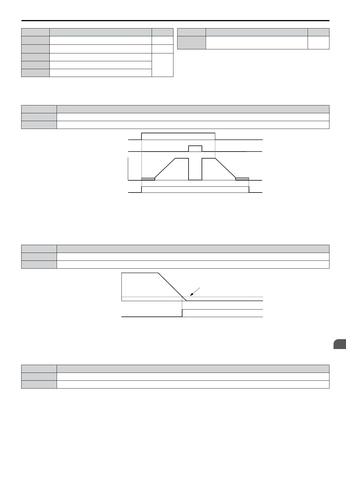
Setting 0: During Run
Output closes when the drive is outputting a voltage.
Status Description
Open Drive is stopped.
Closed A Run command is input or the drive is during deceleration or during DC injection.
ON
ON
OFF
OFF
ONOFF
Run command
Baseblock
command
Output
frequency
During Run
Figure 5.55 During Run Time Chart
Setting 1: Zero Speed
Terminal closes whenever the output frequency falls below the minimum output frequency set to E1-09.
Status Description
Open Output frequency is above the minimum output frequency set to E1-09
Closed Output frequency is less than or equal to the minimum output frequency set to E1-09
OFF
Output frequency
or
motor speed
Zero Speed
ON
E1-09 (Max. Output Frequency)
Figure 5.56 Zero-Speed Time Chart
Setting 2: Speed Agree 1 (f
ref
/f
out
Agree 1)
Closes whenever the actual output frequency is within
the Speed Agree Width (L4-02) of the current frequency reference
regardless of the direction.
Status Description
Open Output frequency does not match the frequency reference while the drive is running.
Closed Output frequency is within the range of frequency reference ± L4-02.
Note: Detection works in both directions, forward and reverse.
5.7 H: Terminal Functions
YASKAWA ELECTRIC SIEP C710606 16C YASKAWA AC Drive – V1000 Technical Manual
187
5
Parameter Details

 Loading...


