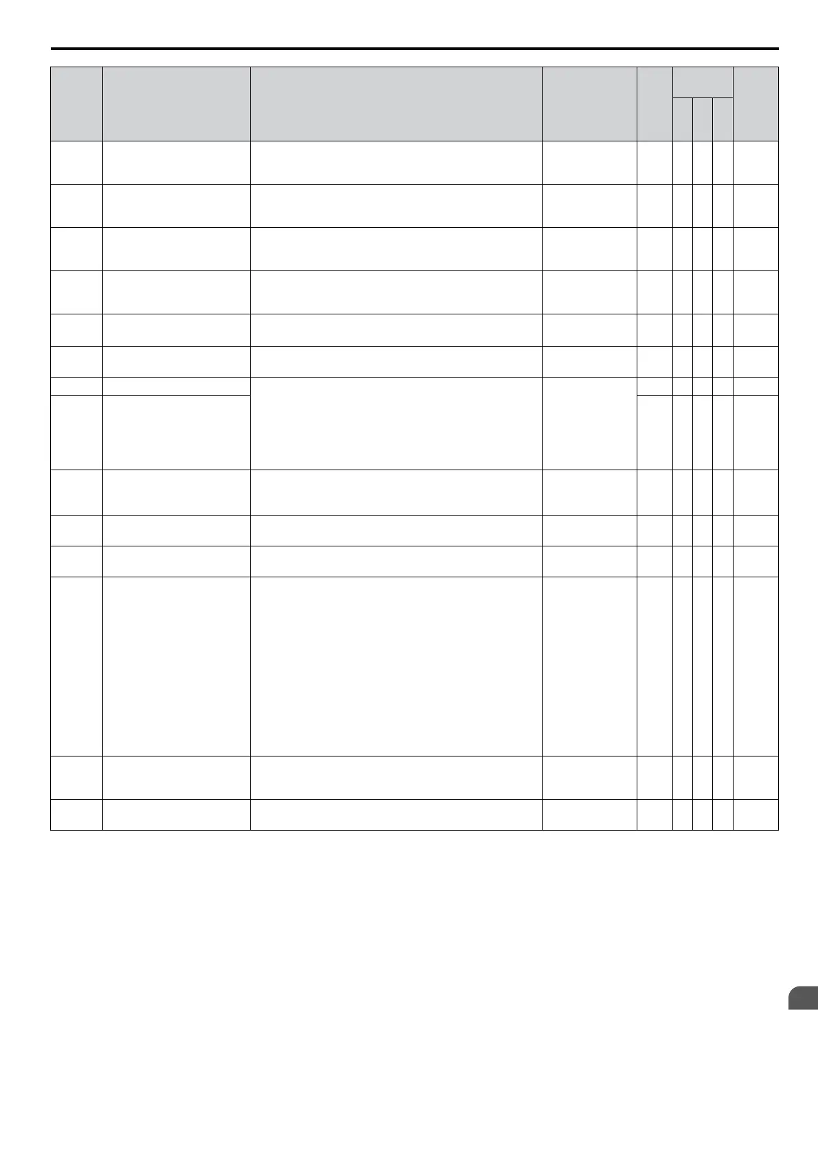
No. Name Description
Analog Output
Level
Unit
Control
Mode
Addr.
Hex
V/
f
O
L
V
P
M
U4-04
Cooling Fan Maintenance
Displays main cooling fan usage time in as a percentage of
their expected performance life. Parameter o4-03 can be
used to reset this monitor.
No signal output
avail.
1% A A A 7E
U4-05 Capacitor Maintenance
Displays main circuit capacitor usage time in as a
percentage of their expected performance life. Parameter
o4-05 can be used to reset this monitor.
No signal output
avail.
1% A A A 7C
U4-06
<5>
Soft Charge Bypass Relay
Maintenance
Displays the soft charge bypass relay maintenance time as
a
percentage of the estimated product life. Parameter o4-07
can be used to reset this monitor.
No signal output
avail.
1% A A A 7D6
U4-07
<5>
IGBT Maintenance
Displays IGBT usage time as a percent of expected
performance
life. Parameter o4-09 can be used to reset this
monitor.
No signal output
avail.
1% A A A 7D7
U4-08
<6>
Heatsink Temperature Displays the heatsink temperature. 10 V: 100 °C 1 °C A A A 68
U4-09 LED Check
Lights all segments of the LED to verify that the display is
working properly.
No signal output
avail.
– A A A 3C
U4-10 kWh, Lower 4 Digits Monitors the drive output power. The value is shown as a
9 digit number displayed across two monitor parameters,
U4-10 and U4-11.
Example:
12345678.9 kWh is displayed as:
U4-10: 678.9 kWh
U4-11: 12345 MWh
No signal output
avail.
kWh A A A 5C
U4-11 kWh, Upper 5 Digits MWh A A A 5D
U4-13 Peak Hold Current Displays the peak hold current during run.
No signal output
avail.
0.01
A
<2>
A A A 7CF
U4-14
Peak Hold Output Frequency Displays the output frequency when operating at the peak
hold current.
No signal output
avail.
0.01
Hz
A A A 7D0
U4-16
Motor Overload Estimate
(oL1)
100% = oL1 detection level
100% = oL1
detection level
0.1% A A A 7D8
U4-18
Frequency Reference Source
Selection
Displays the source for the frequency reference as XY-nn.
X: indicates which reference is used:
1 = Reference 1 (b1-01)
2 = Reference 2 (b1-15)
Y-nn: indicates the reference source
0-01 = Operator (d1-01)
1-01 = Analog (terminal A1)
1-02 = Analog (terminal A2)
2-02 to 17 = Multi-step speed (d1-02 to 17)
3-01 = MEMOBUS/Modbus comm.
4-01 = Option
5-01 = Pulse Input
6-01 = CASE
7-01 = DWEZ
– – A A A 7DA
U4-19
Frequency Reference from
MEMOBUS/Modbus
Comm.
Displays the frequency reference provided by
MEMOBUS/Modbus (decimal).
– – A A A 7DB
U4-20
Option Frequency Reference Displays the frequency reference input by an option card
(decimal).
– – A A A 7DD
B.2 Parameter Table
YASKAWA ELECTRIC SIEP C710606 16C YASKAWA AC Drive – V1000 Technical Manual
375
B
Parameter List

 Loading...


