Equipment and Port Configuration Modem Line Ports (MLP)
Table 12: MLP Troubleshooting and Analysis buttons
To view the following information for the selected DMT pair
Rate Details (on page 13-
50)
Allocated, available and attainable data rates.
Spectral Details (on page
13-51)
Status (Tx mode, EWL length, etc.), Spectral details (US0 Mask,
US PSD, etc.) and US/DS signal power (dBm) measurements
Available only on the ML700 CO. HW, SW, identification and
status information on the CPE side of this copper pair.
Quality Details (on page
13-52)
SLA and actual measurements (noise margin, INP, interleaving,
etc.)
US and DS rates, attenuation and SNR
SC Graphs (on page 13-
54)
Sub-carrier graph analysis options according various user
selected parameters.
INM Graphs (on page
13-53)
Provides histograms of the Impulse Noise.
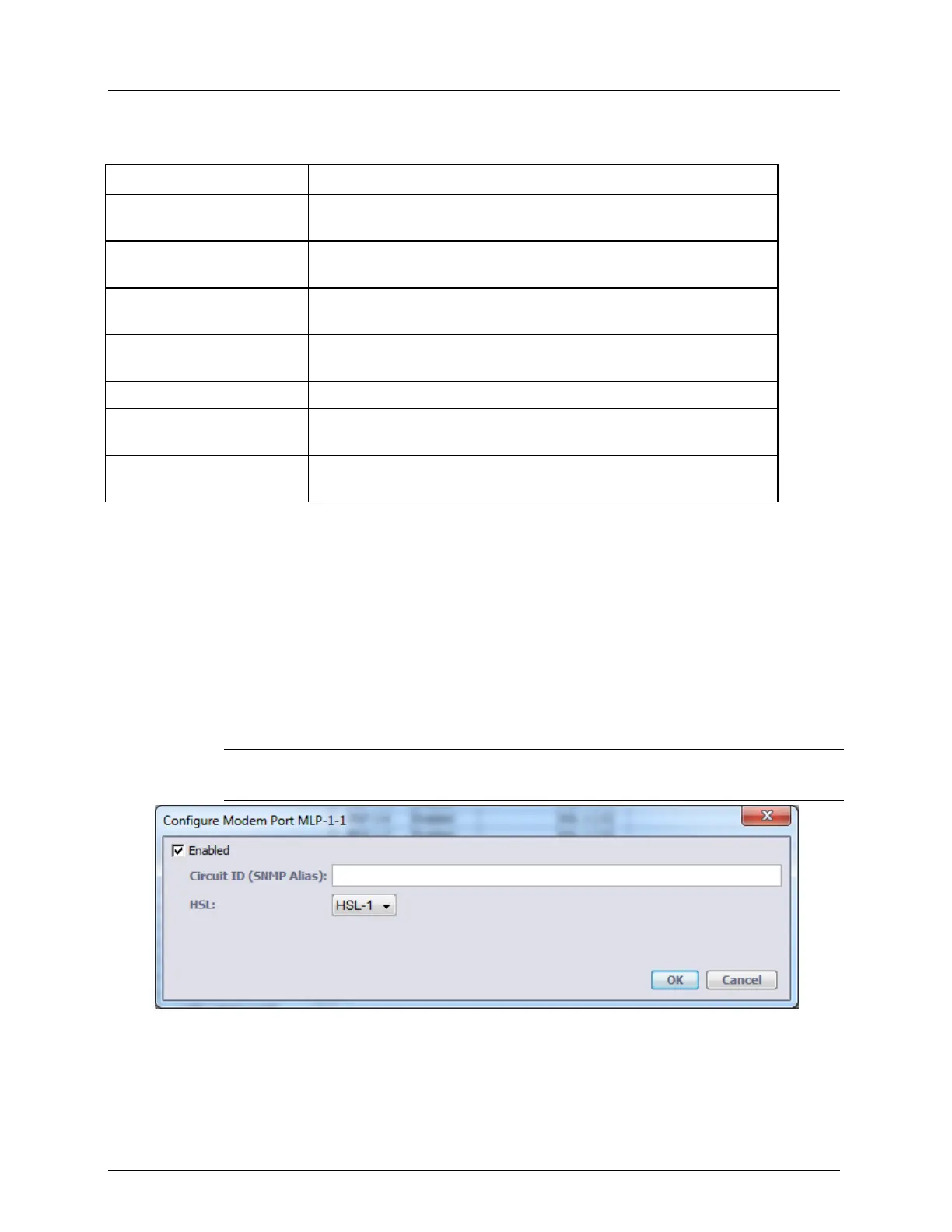
MLP Configuration
This dialog is used to enable or disable modems and to configure modem parameters.
To configure modems
1. In the Network Element tree, select Modem Ports. The Modem Ports pane opens
showing the list of MLPs.
2. Select the modem(s) to be enabled or configured and click the Configure button. The
Configure Modem Port dialog appears.
NOTE: To select more than one MLP at a time, click on the wanted MLPs while holding
the SHIFT button.
3. To disable modems not in use, clear the Enabled checkbox. The definitions will be
retained and reapplied when the MLP is enabled. Note that activated calibration will
remain pending as long as not all enabled modems are synchronized.
4. Click OK.