22 Rockwell Automation Publication 193-UM015E-EN-P - October 2015
Chapter 1 Product Overview
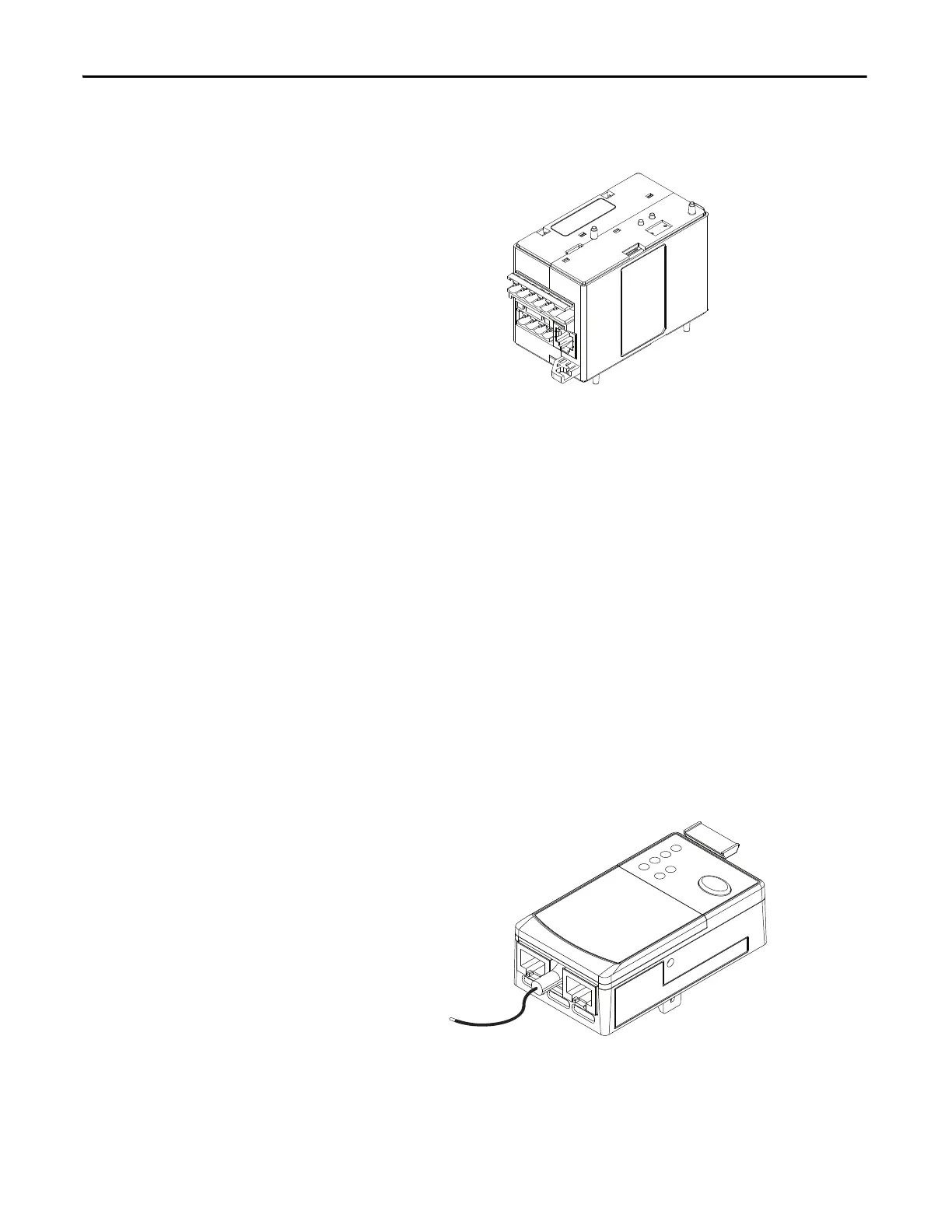
Control Module
Figure 2 - Control Module
The control module is the heart of the E300 relay and can attach to any sensing
module. The control module performs all protection and motor control
algorithms and contains the native I/O for the system. The control module has
two varieties:
• I/O only
• I/O and protec
tion (PTC and External Ground Fault Current Sensing)
The control module is offered in three control voltages:
• 110…120V AC, 50/60Hz
• 220…240V
AC, 50/60Hz
• 24V
DC
Exte
rnal control voltage is required to power the E300 relay and activate the
digita
l inputs.
Communication Module
Figure 3 - Communication Module
The communication module allows the E300 relay to be integrated into an
automation system, and it can attach to any control module. All communication
modules allow you to set the node address with rotary turn dials, and it provides

 Loading...


