Rockwell Automation Publication 193-UM015E-EN-P - October 2015 235
Operating Modes Chapter 5
Reversing Starter (Local I/O) – Three-wire Control
The E300 relay’s Operating Mode Reversing Starter (Local I/O) – Three Wire
Control (Parameter 195 = 42) uses a normally open momentary push button in
Input 0 to energize Output Relay 0, which controls the forward contactor coil. A
normally open momentary push button in Input 1 is used to energize Output
Relay 1, which controls the reversing contactor coil. A normally closed push
button in Input 2 is used to de-energize Output Relay 0 and Output Relay 1.
Both Input 0, Input 1, and Input 2 are momentary signals, so the reversing starter
only energizes if Input 2 is active and Input 0 or Input 1 is momentarily active.
Input 2 must be momentarily de-active before changing to another direction.
InterlockDelay (Parameter 215) defines the minimum time delay when switching
direction.
The reset button of the E300 Operator Station is enabled for this operating
mode.
Rules
1. Available for Control Module firmware v5.000 and higher.
2. Four digital inputs must be available on the Control Module
3. Output Pt00 Assignment (Parameters 202) must be set to Control Relay.
4. Output Pt00 Assignment (Parameters 202) must be set to Control Relay.
5. Overload Trip must be enabled in TripEnableI (Parameter 183).
6. Communication Fault & Idle Override (Parameter 346) must be enabled.
7. Network Fault Override (Parameter 347) must be enabled.
Wiring Diagram
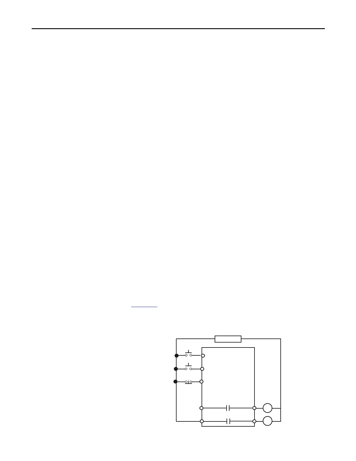
Figure 141 is a wiring diagram of a reversing starter with three wire control and
Output Relay 0 and Output Relay 1 configured as control relays.
Figure 141 - Reversing Starter (Local I/O) – Three-wire Control Wiring Diagram
R13 R14
Relay 0
Run Reverse
E300
IN 1
Stop
Run Reverse
Control Power
IN 2
IN 0
R03 R04
Relay 0
Run Forward
Run Forward

 Loading...


