Rockwell Automation Publication 193-UM015E-EN-P - October 2015 205
Operating Modes Chapter 5
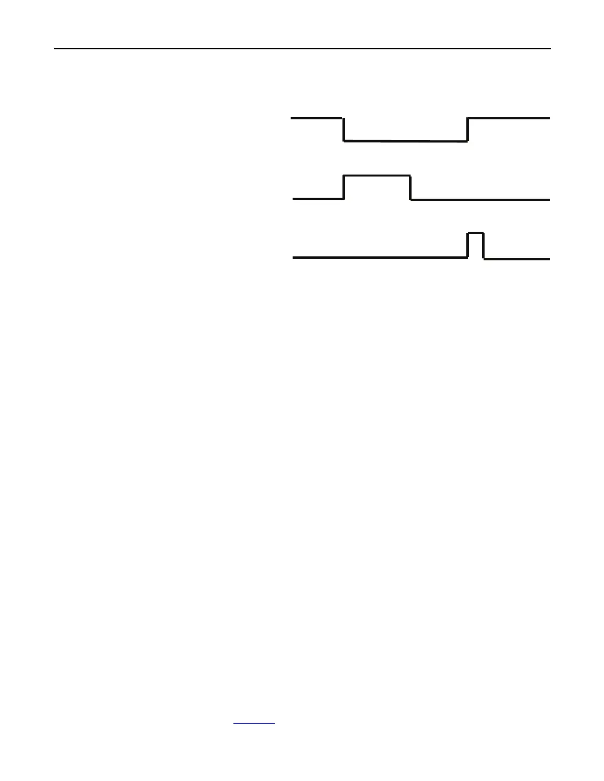
Timing Diagram
Figure 110 - Non-reversing Starter (Custom) Timing Diagram
Reversing Starter Operating
Modes
The non-reversing starter-based operating modes of the E300 relay provide the
control logic for a reversing full voltage starter. Two normally open control relays
control the forward and reverse contactor coils. When a trip event occurs, both
control relays remain open until the E300 receives a trip reset command. There
are 11 reversing starter-based operating modes to choose from:
• Ne
twork
• Network with Feedback
• Operator Station
• Operator Station with Feedback
• Local I/O – Two-wire Control
• Local I/O with Feedback – Two-wire Control
• Local I/O – Three-wire Control
• Network & Operator Station
• Network & Local I/O – Two-wire Control
• Network & Local I/O – Three-wire Control
• Custom
Reversing Starter (Network)
The E300 relay’s Operating Mode Reversing Starter (Network) (Parameter 195 =
5) uses network tags LogicDefinedPt00Data in Output Assembly 144 to control
Relay 0, which controls the forward contactor coil, and LogicDefinedPt01Data in
Output Assembly 144 to control Relay 1, which controls the reversing contactor
coil. Both LogicDefinedPt00Data and LogicDefinedPt01Data are maintained
values, so the reversing starter remains energized when LogicDefinedPt00Data or
LogicDefinedPt01Data has a value of 1. You can program the appropriate state of
the starter when communication is lost using the Network Communication Fault
and Network Communication Idle parameters (Parameters 569 – 573) described
in Chapter 4
.
Trip Relay
Trip Reset
Device
Status0.Trip
Present

 Loading...


