206 Rockwell Automation Publication 193-UM015E-EN-P - October 2015
Chapter 5 Operating Modes
InterlockDelay (Parameter 215) defines the minimum time delay when switching
direction.
The reset button of the E300 Operator Station is enabled for this operating
mode.
Rules
1. Available for Control Module firmware v5.000 and higher.
2. Output Pt00 Assignment (Parameters 202) must be set to Control Relay.
3. Output Pt01 Assignment (Parameters 203) must be set to Control Relay.
4. Overload Trip must be enabled in TripEnableI (Parameter 183).
Wiring Diagram
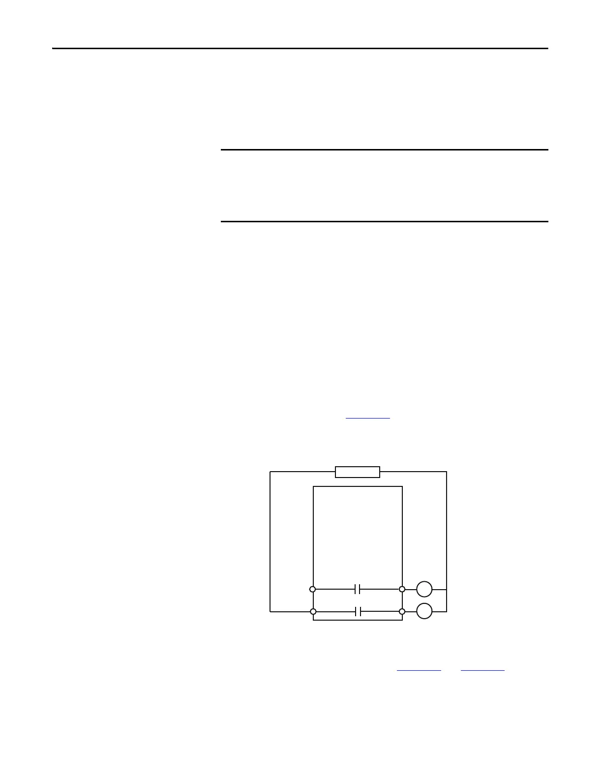
The E300 relay’s Output Relay 0 is wired as a control relay to the forward
contactor and Output Relay 1 is wired as a control relay to the reversing
contactor in which both relays are controlled by the communication network and
open when a trip event occurs. Figure 111
is a wiring diagram of a reversing
starter with Output Relay 0 and Output Relay 1 configured as control relays.
Figure 111 - Reversing Starter (Network) Wiring Diagram
DeviceLogix Program
The DeviceLogix program that is shown in Figure 112 and Figure 113 is
automatically loaded and enabled in the E300 on power-up or when Operating
Mode (Parameter 195) is set to a value of 5.
The Reversing Starter (Network) operating mode uses the value in network tag
LogicDefinedPt00Data or LogicDefinedPt01Data to control the starter. When
communication between an automation controller and the E300 is restored,
the starter energizes if the value in LogicDefinedPt00Data or
LogicDefinedPt01Data is set to 1.
R13 R14
Relay 0
Run Reverse
E300
Control Power
R03 R04
Relay 0
Run Forward

 Loading...


