Rockwell Automation Publication 193-UM015E-EN-P - October 2015 157
Operating Modes Chapter 5
Figure 56 - Control Relay Wiring Diagram
DeviceLogix™ Program
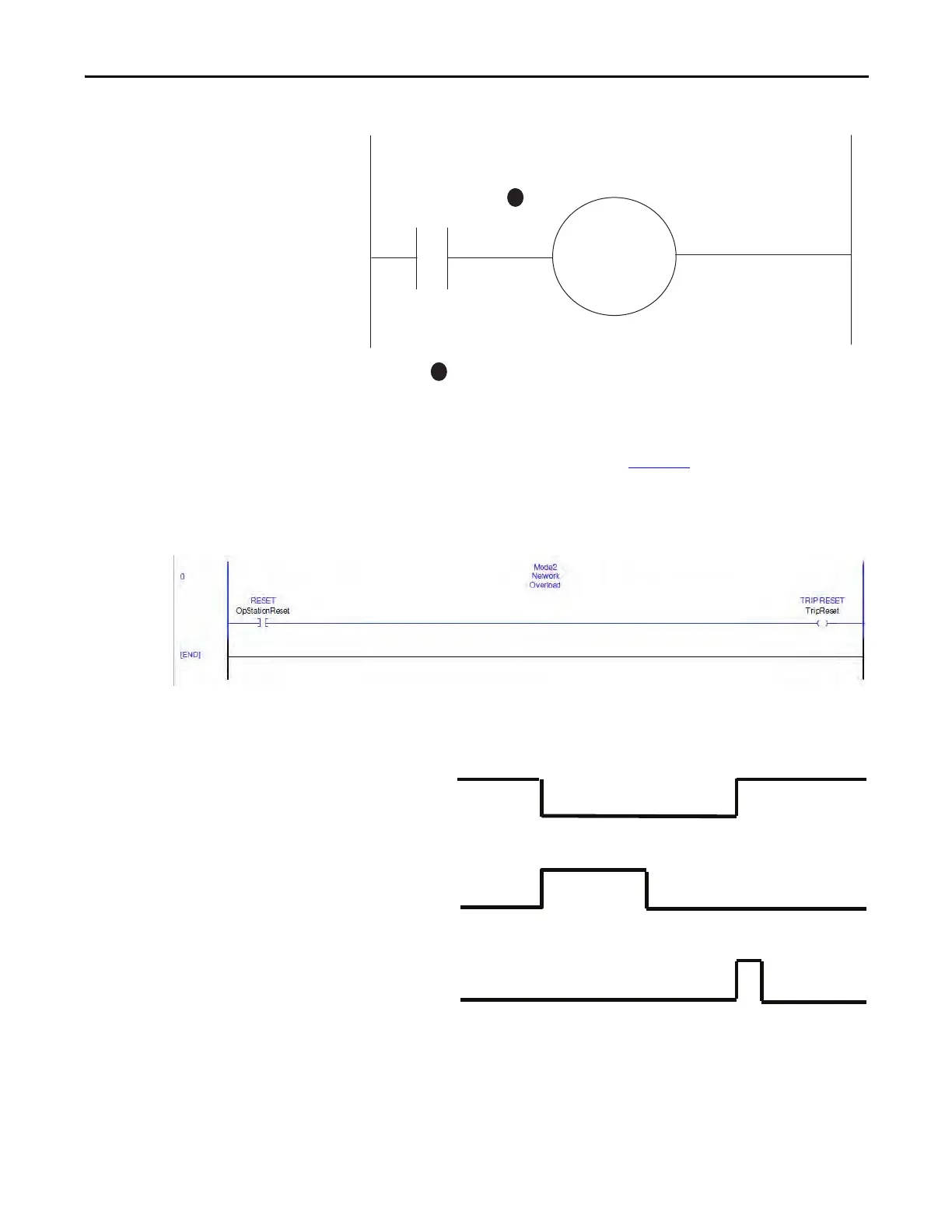
The DeviceLogix program that is shown in Figure 57 is automatically loaded and
enabled in the E300 on power-up or when Operating Mode (Parameter 195) is
set to a value of 2.
Figure 57 - Overload (Network) DeviceLogix Program
Timing Diagram
Figure 58 - Overload (Network) Timing Diagram
Overload (Operator Station)
The E300 relay’s Operating Mode Overload (Operator Station) (Parameter 195 =
26) operates as a traditional overload relay with one output relay that is assigned
Relay 0
Configured as a
Control Relay
R03 R04
A1
A2
M
1
1
Contact shown with supply voltage applied.
Trip Relay
Trip Reset
Device
Status0.Trip
Present

 Loading...


