EasyManuals Logo

Allen-Bradley E300 User Manual

Allen-Bradley E300
736 pages
To Next Page IconTo Next Page
To Previous Page IconTo Previous Page
Page #29 background imageLoading...
Page #29 background image
Rockwell Automation Publication 193-UM015E-EN-P - October 2015 29
Installation and Wiring Chapter 2
Base Relay Assembly
The following section illustrates the E300 relay base relay assembly instructions.
Control Module to Sensing
Module Assembly
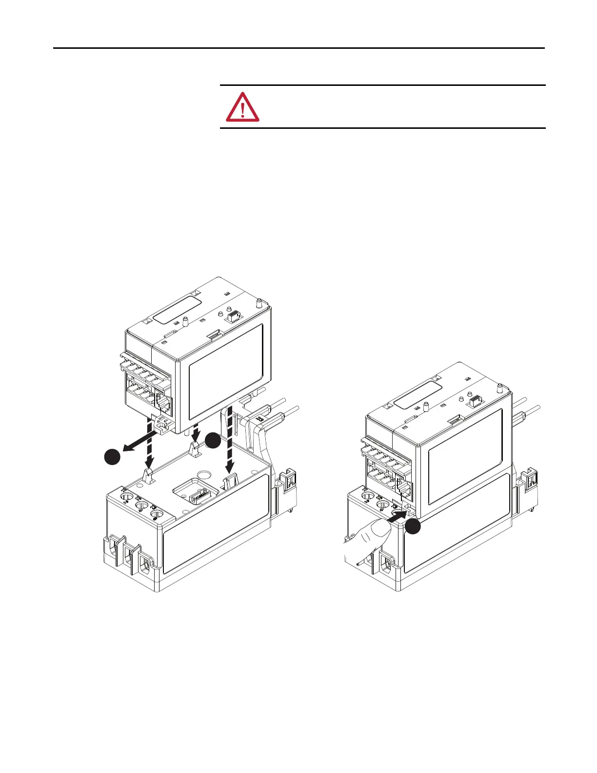
You can connect any E300 relay Control Module to any E300 relay Sensing
Module. The following illustrations show the steps that are required to make this
connection.
Figure 6 - Control Module to Sensing Module Assembly
ATTENTION: The earth ground terminal of the E300 relay shall be connected to
a solid earth ground via a low-impedance connection.
2
3
1

Table of Contents

Other manuals for Allen-Bradley E300

Questions and Answers:

Question and Answer IconNeed help?

Do you have a question about the Allen-Bradley E300 and is the answer not in the manual?

Allen-Bradley E300 Specifications

General IconGeneral
TypeElectronic Overload Relay
MountingDIN Rail or Panel Mount
Protection ClassIP20
Voltage Range24…690 V AC/DC
Communication OptionsEtherNet/IP, DeviceNet
ProtectionOverload, phase loss, ground fault
Operating Temperature-20°C to 60°C

Related product manuals