24 Rockwell Automation Publication 193-UM015E-EN-P - October 2015
Chapter 1 Product Overview
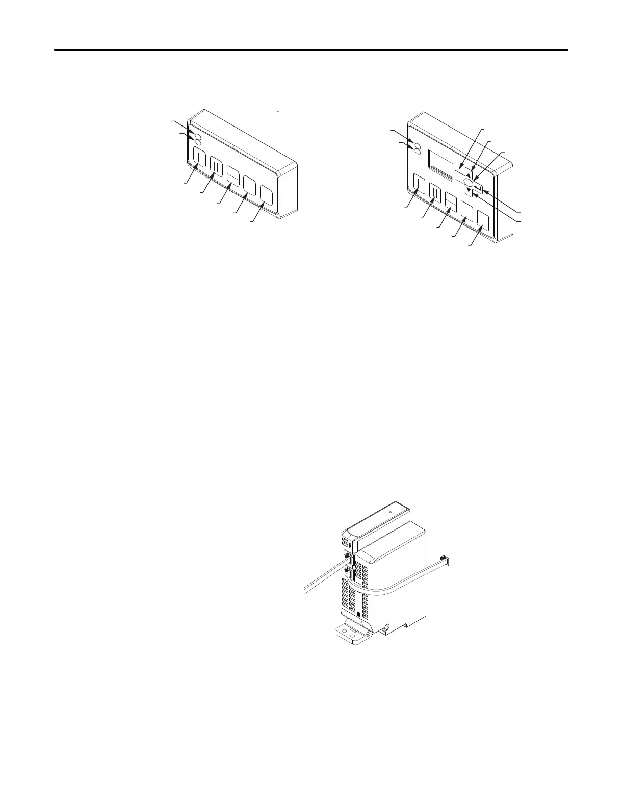
Optional Operator Station
Figure 4 - Operator Stations
The E300 relay offers you the capability to add one operator interface to the
Expansion Bus. You can choose between two types of operator stations: Control
Station or a Diagnostic Station. Both types of operator stations mount into a
standard 22 mm push button knockout, and they provide diagnostic status
indicators that allow you to view the status of the E300 relay from the outside of
an electrical enclosure. Both operator stations provide push buttons that can be
used for motor control logic, and they both can be used to upload and download
parameter configuration data from the base relay.
The Diagnostic Station contains a display and navigation buttons that allows you
to view and edit parameters in the base relay. The Diagnostic Station requires
Control Module firmware v3.000 or higher.
Optional Expansion Bus Power Supply
Figure 5 - Expansion Bus Power Supply
The E300 relay expansion bus provides enough current to operate a system that
has (1) Digital Expansion Module and (1) Operator Station. An E300 relay
system that contains more expansion modules needs supplemental current for the
Expansion Bus. the E300 relay offers you two types of Expansion Bus Power
Supplies: AC (110…240V AC, 50/60 Hz) and DC (24V DC). One Expansion
Bus Power Supply supplies enough current for a fully loaded E300 relay
Expansion Bus (four Digital Expansion Modules, four Analog Expansion
Start Forward / Speed 1
Start Reverse / Speed 2
Local / Remote
Stop
Reset
Start Forward / Speed 1
Start Reverse / Speed 2
Local / Remote
Stop
Up
Down
Reset
Escape
Power LED
Trip / Warn LED
Power LED
Trip / Warn LED
Enter
Select
0
RESET
LOC AL
REMOTE
0
RESET
SELECT
ESC
REMOTE
LOC AL
Control Station Diagnostic Station

 Loading...


