176 Rockwell Automation Publication 193-UM015E-EN-P - October 2015
Chapter 5 Operating Modes
Timing Diagram
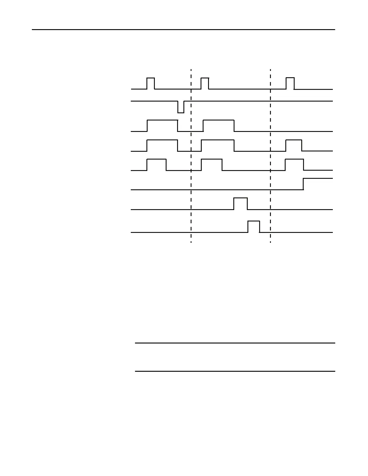
Figure 81 - Non-reversing Starter (Operator Station) with Feedback Timing Diagram
Non-reversing Starter (Local I/O) – Two-wire Control
The E300 relay’s Operating Mode Non-Reversing Starter (Local I/O) – Two Wire
Control (Parameter 195 = 36) uses Input 0 to control Output Relay 0, which
controls the contactor coil. Input 0 is a maintained value, so the non-reversing
starter remains energized when Input 0 is active.
The reset button of the E300 Operator Station is enabled for this operating
mode.
Rules
1. Available for Control Module firmware v5.000 and higher.
2. Output Pt00 Assignment (Parameters 202) must be set to Control Relay.
3. Overload Trip must be enabled in TripEnableI (Parameter 183).
4. Communication Fault & Idle Override (Parameter 346) must be enabled.
Trip Event Feedback Timeout
Start
Stop
Feedback (IN0)
Relay 0
Timer
Feedback
Timeout Trip
Trip Status
Trip Reset
The Non-reversing Starter (Local I/O) – Two-wire Control operating mode uses
the signal from Input 0 to control the starter. When an E300 powers up, the
starter energizes if Input 0 is active.

 Loading...


