Rockwell Automation Publication 193-UM015E-EN-P - October 2015 239
Operating Modes Chapter 5
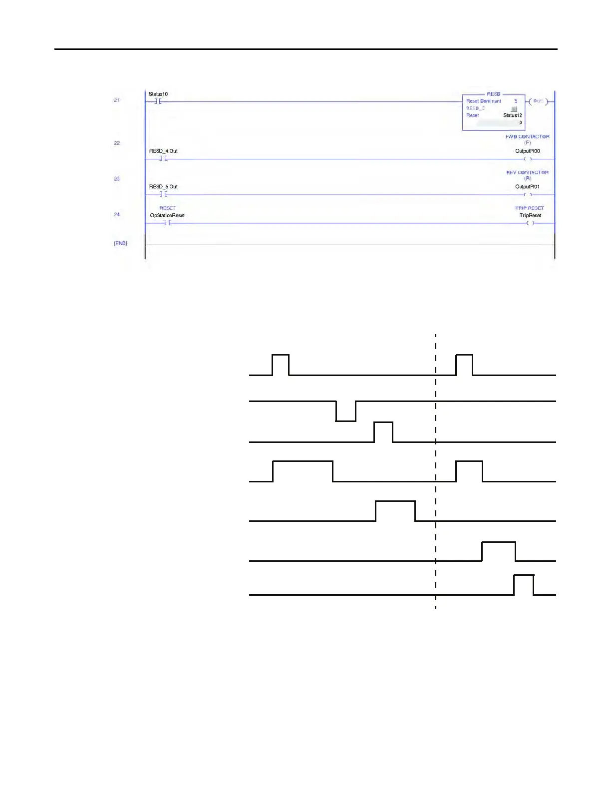
Figure 144 - Reversing Starter (Local I/O) – Three-wire Control DeviceLogix Program, Part C
Timing Diagram
Figure 145 - Reversing Starter (Local I/O) – Three-wire Control Timing Diagram
Reversing Starter (Network & Operator Station)
The E300 relay’s Operating Mode Reversing Starter (Network& Operator Station)
(Parameter 195 = 13) in Remote control mode uses network tags
LogicDefinedPt00Data in Output Assembly 144 to control Relay 0, which
controls the forward contactor coil, and LogicDefinedPt01Data in Output
Assembly 144 to control Relay 1, which controls the reversing contactor coil.
Forward
Trip Event
Stop
FWD (Relay 0)
Trip Status
Trip Reset
REV (Relay 1)
Reverse

 Loading...


