Rockwell Automation Publication 193-UM015E-EN-P - October 2015 559
Chapter 10
EtherNet/IP Communication
Introduction
This chapter provides the necessary instructions to successfully connect the
E300™ Electronic Overload Relay EtherNet/IP Communication Module
(Catalog Number 193-ECM-ETR) to an Ethernet network and configure it to
communicate to an EtherNet/IP scanner such as an Allen-Bradley Logix
controller.
Network Design
The E300 relay EtherNet/IP Communication Module has dual Ethernet ports
that function as an Ethernet switch with RJ45 ports to connect Ethernet cable
CAT5 type or better to. Rockwell Automation offers a wide variety of Allen-
Bradley Ethernet patch cables with its Bulletin 1585 line of Ethernet cables
(http://ab.rockwellautomation.com/Connection-Devices/RJ45-Network-
Media).
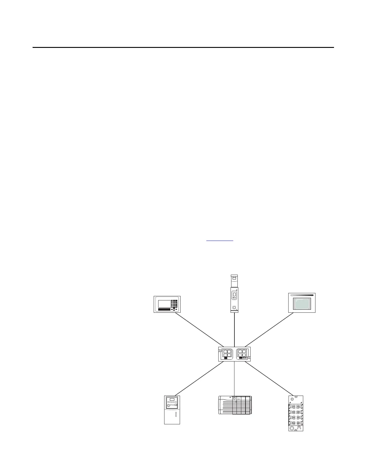
The E300 relay EtherNet/IP Communication Module supports a Star, Linear,
and Ring Ethernet topology. Figure 213
shows an example of a Star Ethernet
Topology, in which all Ethernet nodes wire back to a central Ethernet switch,
hub, or router.
Figure 213 - Star Ethernet Topology

 Loading...


