256 Rockwell Automation Publication 193-UM015E-EN-P - October 2015
Chapter 5 Operating Modes
Wiring Diagram
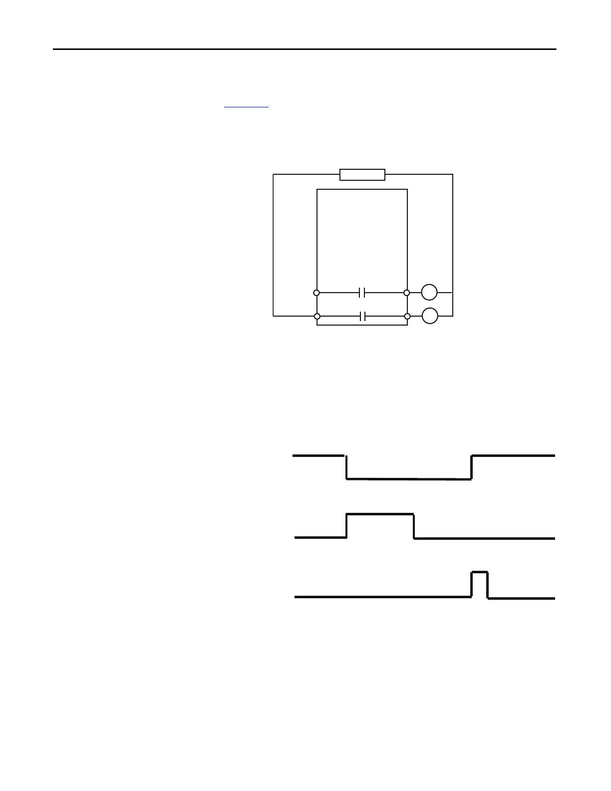
Figure 159 is a wiring diagram of a reversing starter with Output Relay 0 and
Output Relay 1 configured as control relays. Both Output Relay 0 and Output
Relay 1 go to an open state when there is a trip event.
Figure 159 - Reversing Starter (Custom) Wiring Diagram
DeviceLogix Program
The last saved DeviceLogix program is executed in the E300 on power-up or
when Operating Mode (Parameter 195) is set to a value of 50.
Timing Diagram
Figure 160 - Reversing Starter (Custom) Timing Diagram
Two-speed Starter Operating
Modes
The two-speed starter-based operating modes of the E300 relay provide the
control logic for a two-speed full-voltage starter. Two normally open control
relays control the high-speed and low-speed contactor coils. When a trip event
occurs, both control relays remain open until the E300 receives a trip reset
command. There are 11 two-speed starter-based operating modes to choose
from:
R13 R14
Relay 1
Run Reverse
E300
Control Power
R04
Relay 0
Run Forward
R03
Trip Relay
Trip Reset
Device
Status0.Trip
Present

 Loading...


