Rockwell Automation Publication 193-UM015E-EN-P - October 2015 271
Operating Modes Chapter 5
Timing Diagram
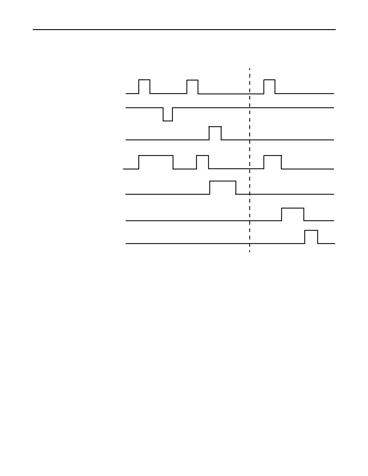
Figure 174 - Two-speed Starter (Operator Station) Timing Diagram
Two-speed Starter (Operator Station) with Feedback
The E300 relay’s Operating Mode Two Speed Starter (Operator Station) with
Feedback (Parameter 195 = 34) uses the E300 Operator Station’s “I” and “0” keys
to control Relay 0, which controls the contactor coil. These keys are momentary
push buttons, so the two-speed starter remains energized when you release the “I”
button. The E300 issues a trip or warning event if the E300 Operator Station
disconnects from the base relay.
The auxiliary contact from the two-speed starter’s contactor is wired into Input
0. If a feedback signal is not received before the time identified in Feedback
Timeout (Parameter 213), then the E300 issues a trip or warning event.
InterlockDelay (Parameter 215) defines the minimum time delay when switching
direction.
The E300 Operator Station’s Reset button is enabled, and the Local/Remote
yellow LED is illuminated to indicate that the operator station is being used for
local control.
Run Fast
Trip Event
Stop
Fast (Relay 0)
Trip Status
Trip Reset
Slow (Relay 1)
Run Slow

 Loading...


