Rockwell Automation Publication 193-UM015E-EN-P - October 2015 33
Installation and Wiring Chapter 2
Set the module number dial of the Expansion Digital Module to a unique digital
module number (D1-D4). If the Expansion Digital Module is the last device on
the Expansion Bus, set the module number to the value that enables the internal
terminating resistor (D1T-D4T). A power cycle is required when changes are
made to the module number dial.
Set the module number dial of the Expansion Analog Module to a unique analog
module number (A1-A4). If the Expansion Analog Module is the last device on
the Expansion Bus, set the module number to the value that enables the internal
terminating resistor (A1T-A4T). A power cycle is required when changes are
made to the module number dial.
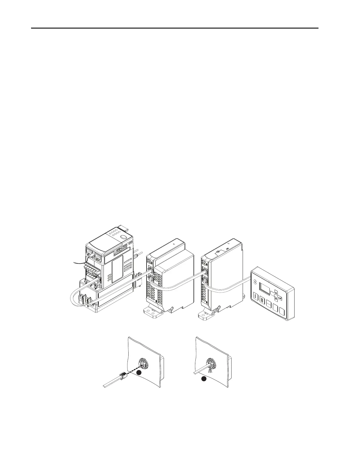
Connect the E300 Base Relay to the Expansion Module’s Input Port using the
supplied Expansion Bus cable. Add the next Expansion Module by connecting
the supplied Expansion Bus cable to the Output Port of the previous Expansion
Module and into the Input Port of the additional Expansion Module. The
Operator Station is the last device on the E300 relay Expansion Bus; it only has
an Input Port with an internal Expansion Bus terminating resistor.
If the user-supplied Expansion Bus cable is not long enough for the installation,
1-meter (Cat. No. 193-EXP-CBL-1M) and 3-meter (Cat. No.
193-EXP-CBL-3M) Expansion Bus cables are available as accessories. The E300
relay expansion bus can support a maximum distance of 5 meters (16 ft.).
Figure 12 - Expansion Bus Network Installation
0
RESET
SELECT
ESC
REMOTE
LOCA L
Click
1
2

 Loading...


