534 Rockwell Automation Publication 193-UM015E-EN-P - October 2015
Chapter 8 Metering and Diagnostics
Table 526 - Analog Module 1 – Input Channel 01 (Parameter 112)
Analog Module 1 – Input Channel 02
Analog Module 1 – Input Channel 02 (Parameter 113) reports the monitored
value of Analog Module 1 – Input Channel 02.
Table 527 - Analog Module 1 – Input Channel 02 (Parameter 113)
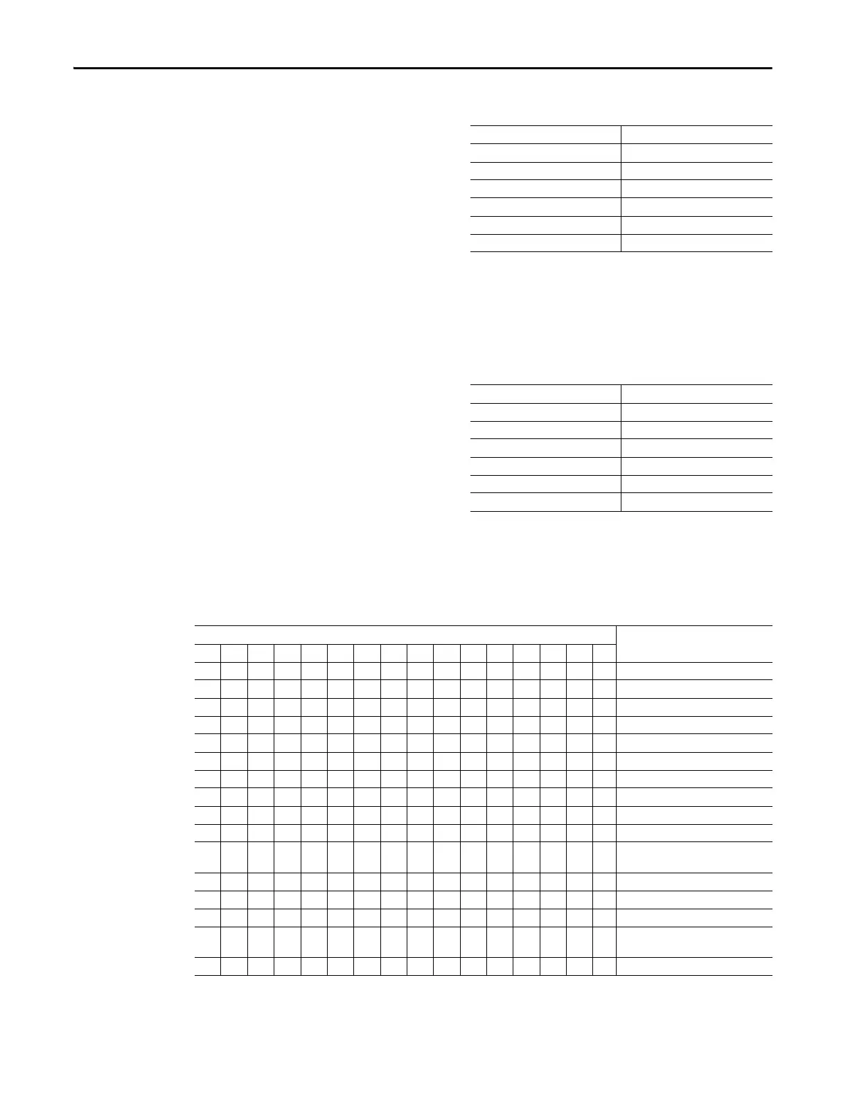
Analog Module 1 Status
Analog Module 1 Status (Parameter 123) reports the status of Analog Module 1.
Table 528 - Analog Module 1 Status (Parameter 123)
Default Value 0
Minimum Value -32768
Maximum Value 32767
Parameter Type INT
Size (Bytes) 2
Scaling Factor 1
Units
Default Value 0
Minimum Value -32768
Maximum Value 32767
Parameter Type INT
Size (Bytes) 2
Scaling Factor 1
Units
Bit
Function
1514131211109876543210
XInput Channel 00 Open Circuit
XInput Channel 00 Over Range
XInput Channel 00 Under Range
XInput Channel 01 Open Circuit
XInput Channel 01 Over Range
XInput Channel 01 Under Range
XInput Channel 02 Open Circuit
XInput Channel 02 Over Range
XInput Channel 02 Under Range
XOutput Channel 00 Open Circuit
X
Output Channel 00 Hold Last State
Mode Active
XOutput Channel 00 Over Range
XOutput Channel 00 Under Range
XAnalog Module Configured
X
Analog Module Warning (Module
Number Dial Changed)
XAnalog Module Faulted

 Loading...


