Low Energy Tests Running a Script in Standard Mode
7-46 PN: 13000-00205 Rev. N MT8852B Operation Manual
Max -ve offset: Displays the frequency error of the single packet that had the greatest
negative error of all those measured.
Drift rate: Displays the maximum drift rate between any two 10-bit groups in the
packet, separated by 50 us. This value is the peak held worst-case
value for packets measured during the test.
Init drift rate: Displays the drift rate between the average frequency of the 8
preamble bits of the packet and the average frequency of the first 10-bit
group in the payload This value is the peak held worst-case value for
packets measured during the test.
Drift: Displays the difference between the average frequency of the 8
preamble bits of the packet and the average frequency of any 10 bits in
the payload field of the same packet. This value is the peak held
worst-case value for packets measured during the test.
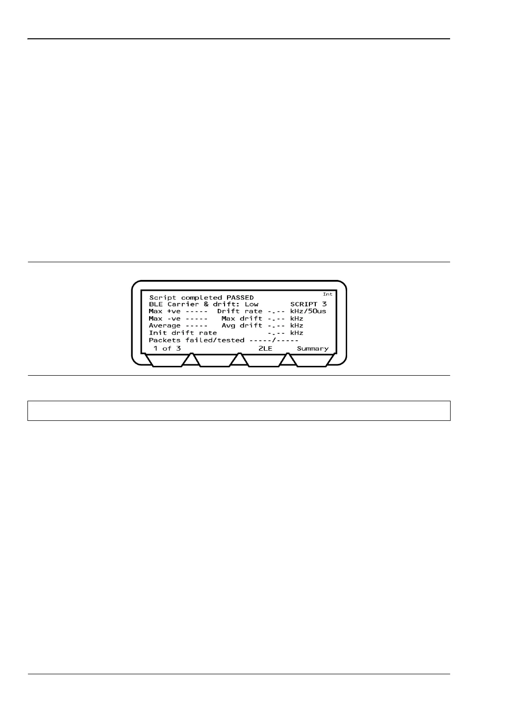
3. Press the [Extended] soft key to display more detailed test results. An example of the
first extended page for the carrier drift test is shown below.
4. Page through the extended screens with the soft key in the normal manner, or press the
[Summary] soft key to revert to the initial summary page.
Figure 7-64. Low Energy Carrier Drift Extended Results
Note “Packets Tested” refers to the total of all packets tested.