DL205 Analog Manual, 7th Edition Rev. D
5-8
Chapter 5: F2-08AD-2, 8-Ch. Analog Voltage Input
1
2
3
4
5
6
7
8
9
10
11
12
13
14
A
b
C
D
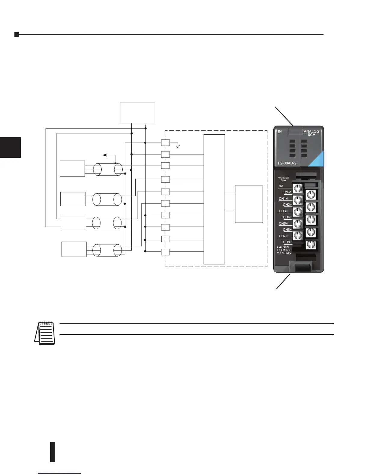
Wiring Diagram
The F2-08AD-2 module has a removable connector to simplify wiring the module. Just squeeze
the top and bottom retaining clips and gently pull the connector from the module. Use the
following diagram to connect the field wiring
NOTE: Connect unused channels (CH5+, CH6+, CH7+, CH8+ in this diagram) to common (0VDC).
1
2
3
4
5
6
7
8
9
10
11
12
13
14
A
b
C
D
ADC
Voltage
Transmitter
Voltage
Transmitter
Voltage
Transmitter
Voltage
Transmitter
CH1
CH3
+
CH5
+
CH7
+
0 VDC
24 VDC
+
-
CH2
CH4
+
CH6
+
CH8
+
CH1
CH2
CH3
CH4
24VDC
Analog Multiplexer
+
+
0 V
3-wire
2-wire
4-wire
3-wire
+
-
+
+
+
+
+
+
-
-
-
-
+24V
CH2+
CH4+
CH6+
CH8+
0V
CH1+
CH3+
CH5+
CH7+
F2-08AD-2
IN ANALOG
8CH
10-30VDC
5mA
ANALOG IN
0-5.0 - 10VDC
+/-5, +/-10VDC
 Loading...

