DL205 Analog Manual, 7th Edition Rev. D
15-23
Chapter 15: F2-8AD4DA-1 8-Ch. In / 4-Ch. Out Analog Current Combination
1
2
3
4
5
6
7
8
9
10
11
12
13
14
15
B
C
D
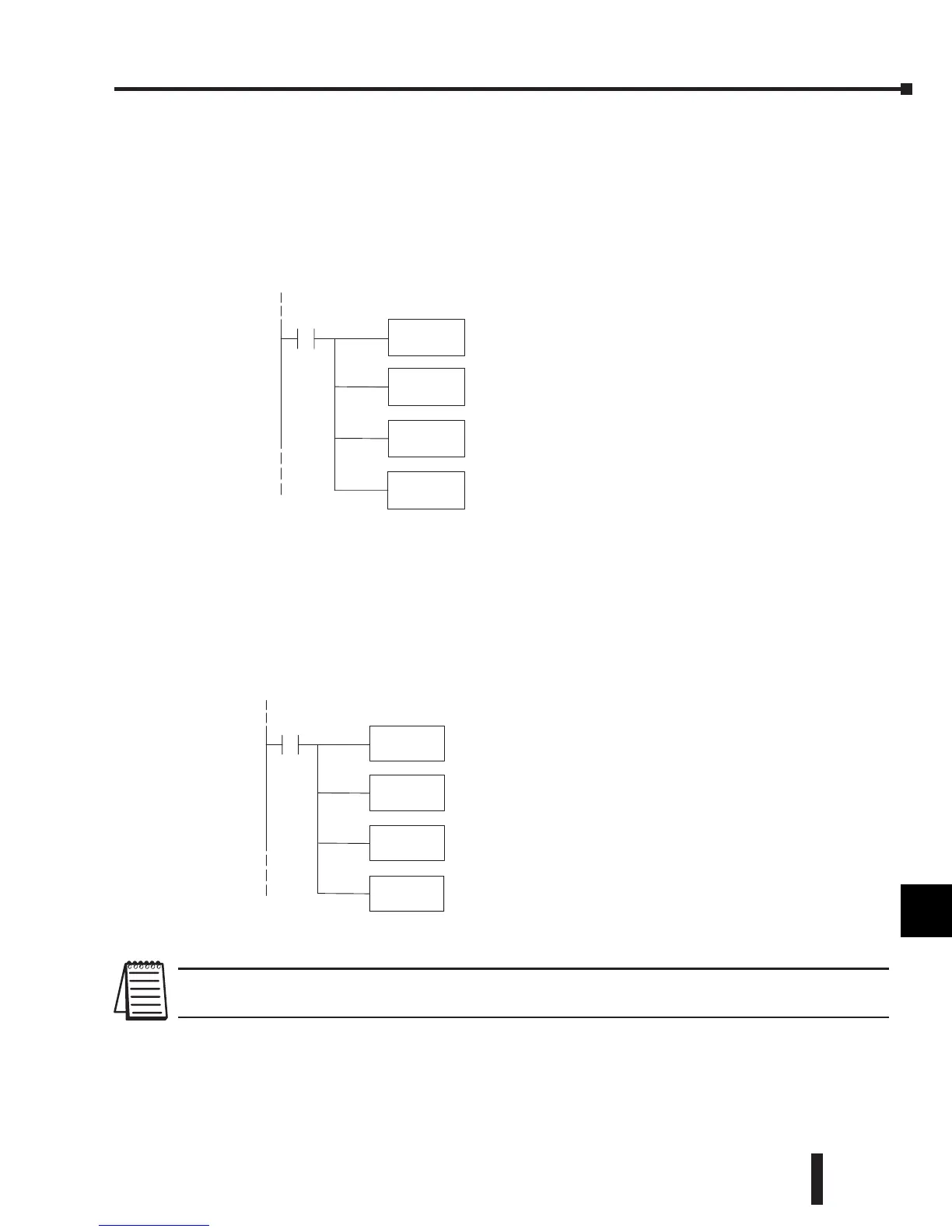
Input Engineering Unit Conversion Example 1:
Data format = BCD,
Channel 1 data memory location = V2000,
Channel 1 resolution = 12 bits,
Channel 1 engineering units = 0.0–140.0 PSI,
Channel 1 input device = 0–20 mA transmitter
Input
Engineering Unit Conversion Example 2:
Data format = binary,
Channel 1 data memory location = V2000,
Channel 1 resolution = 14 bits,
Channel 1 engineering units = 0.0–140.0 PSI,
Channel 1 input device = 0–20 mA transmitter
NOTE: The above examples use SP1 (which is always on) as a permissive contact for the engineering unit conversions. X, C, etc.
could also be used as a permissive contact.
1
2
3
4
5
6
7
8
9
10
11
12
13
14
15
b
C
D
MUL
K1400
Multiply by 1400;
EU range X10for implieddecimal.
DIV
K4095
Divide by 4095;
12 bit digitalrange for0-- 20 mA.
OUT
V2100
StoreinputEUvalue in V2100.
LD
V2000
SP1
Loadinput channel1digitalvalue intoaccumulator.
MULB
K578
Multiply by 1400 [hex 578];
EU range X10for implied decimal.
DIVB
K3FFF
Divide by 16383[hex3FFF];
14 bit digitalrange for0-- 20 mA.
(Use 65535[KFFFF] for16bit;4095 [KFFF]for 12 bit.)
LD
V2000
SP1
Loadinput channel1digitalvalue intoaccumulator.
OUT
V2100
StoreinputEUvalue in V2100.
 Loading...

