DL205 Analog Manual, 7th Edition Rev. D
2-8
Chapter 2: F2-04AD-1, F2-04AD-1L, 4-Channel Analog Current Input
1
2
3
4
5
6
7
8
9
10
11
12
13
14
A
B
C
D
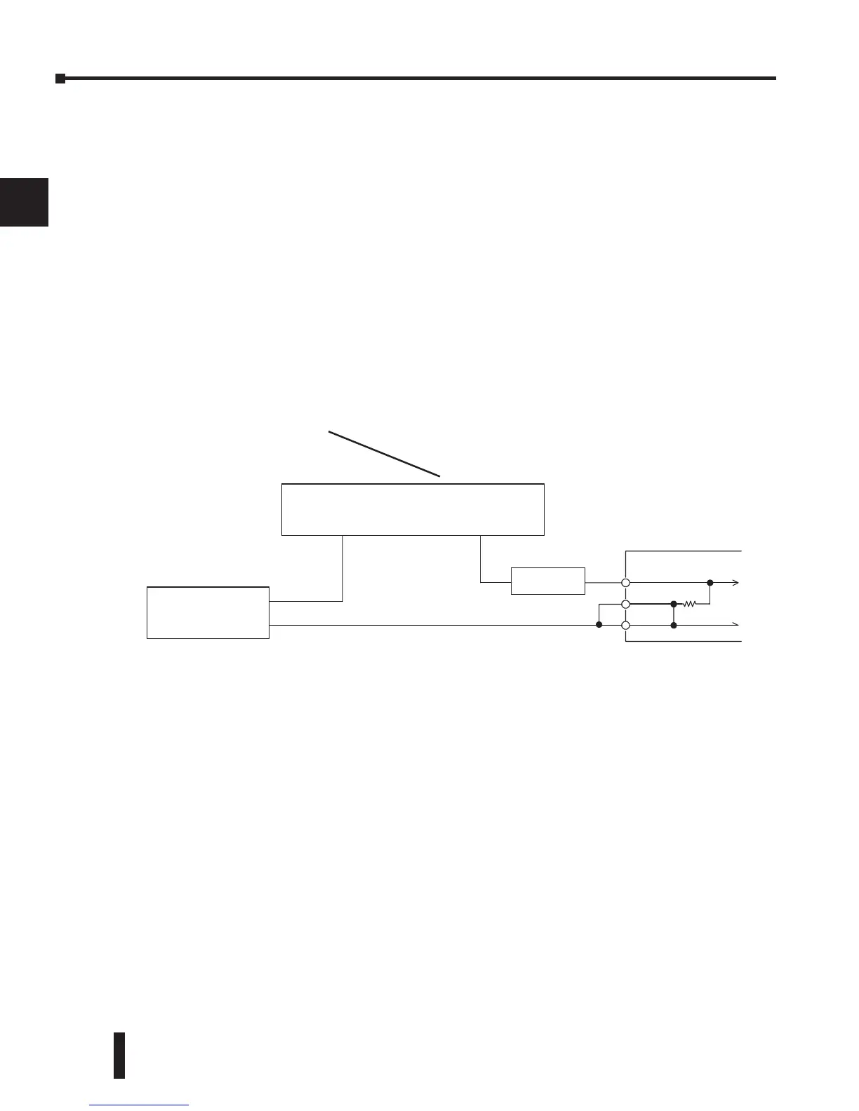
Current Loop Transmitter Impedance
Standard 4–20 mA transmitters and transducers can operate from a wide variety of power
supplies. Not all transmitters are alike and the manufacturers often specify a minimum loop
or load resistance that must be used with the transmitter.
The F2-04AD-1, provides 250 q resistance for each channel. If the transmitter being used
requires a load resistance below 250 q, it is not necessary to make any adjustments. However,
if the transmitter requires a load resistance higher than 250 q, a resistor will need to be added
in series with the input.
Consider the following example for a transmitter being operated from a 30 VDC supply
with a recommended load resistance of 750 q. Since the module has a 250 q resistor, an
additional resistor needs to be added.
1
2
3
4
5
6
7
8
9
10
11
12
13
14
A
b
C
D
0V
+30V
DC Supply
Two-wireTransmitter
+--
ModuleChannel
R
250
CH1--
0V
CH1+
R = Tr - Mr R - Resistor to add
R = 750 - 250 Tr - Transmitter Requirement
R M 500 Mr - Module resistance (internal 250 q)
 Loading...

