DL205 Analog Manual, 7th Edition Rev. D
9-5
Chapter 9: F2-02DA-2, F2-02DA-2L, 2-Channel Analog Voltage Output
1
2
3
4
5
6
7
8
9
10
11
12
13
14
A
b
C
D
Setting the Module Jumpers
The F2-02DA-2 (L) Analog Output module uses jumpers for selecting the voltage ranges for
each channel. The range of each channel can be independently set. Available operating ranges
are 0–5V, 0–10V, ±5V, and ±10V.
There are three jumpers for each channel. Two sets are on the top board, and the third set
is along the edge of the bottom board with the black D-shell backplane connector. Install or
remove these jumpers to select the desired range. Unused jumpers can be stored on a single
pin so they do not get lost.
• Two of the top board jumpers are labeled “UNI / ±5” and there is one for each channel.
• The two bottom board jumpers are labeled “UNI” and there is one for each channel. These
jumpers determine the format of the channel output data, and the effect of their settings is
independent from that of the other jumpers on the module. With a UNI jumper removed, the
corresponding channel requires data values in the range of
±2047. With a UNI jumper
installed, the channel requires data values in the range of 0–4095.
• The other two top board jumpers are labeled “BI-P 0-5” and there is one for each channel.
These jumpers each have three possible settings (including jumper removed) since there are
three pins.
NOTE: It is important to set the module jumpers correctly. The module will not operate correctly if the jumpers are not
properly set for the desired voltage range.
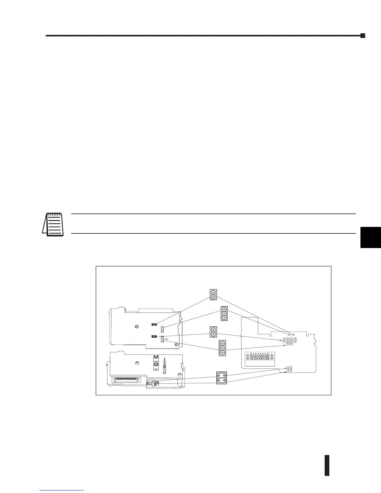
This figure shows the jumper locations. See the table on the following page to determine the
proper settings for your application.
1
2
3
4
5
6
7
8
9
10
11
12
13
14
A
b
C
D
Jumper locations have moved.
F2-02DA-2
CH1 – UNI
CH2 – UNI
CH1 CH1 CH2 CH2
UNI UNI
BI BI
CH2
CH1
CH2
UNI
BI
BI
UNI
F2-02DA-2
New Single PCB Design and Jumper Locations
Date Code Affected: mmyyF and later
CH1
UNI
CH1
BI
CH2
BI
CH2
UNI
 Loading...

