DL205 Analog Manual, 7th Edition Rev. D
16-24
Chapter 16: F2-8AD4DA-2, 8-Ch. In / 4-Ch. Out Analog Voltage Combination
1
2
3
4
5
6
7
8
9
10
11
12
13
14
15
16
C
D
1
2
3
4
5
6
7
8
9
10
11
12
13
14
15
16
C
D
Input Engineering Unit Conversion Example 3:
Data format = binary,
Channel 1 data memory location = V2000,
Channel 1 resolution = 16 bits,
Channel 1 engineering units = 0.0–140.0 PSI,
Channel 1 input device = 0–5V or 0–10V transmitter.
Using the Input Track and Hold Feature
The input Track and Hold feature allows the individual inputs to be separately configured
to maintain their maximum or minimum data values. If No Track and Hold is selected, the
present real time value of the input will be stored in the input data V-memory location. If
Track and Hold minimum value is selected, the first input value less than or equal to full scale
will be read and maintained until a lower value is measured, or until Track and Hold is reset.
If maximum value is selected, the first input value greater than or equal to zero will be read and
maintained until a higher value is measured, or until Track and Hold is reset.
To reset Track and Hold, write a value of one to the Track and Hold selection high and low
bits. When Track and Hold is reset, the module will display the real-time input value. When
the selection is changed from reset to minimum value or maximum value, the input will start
over as described previously.
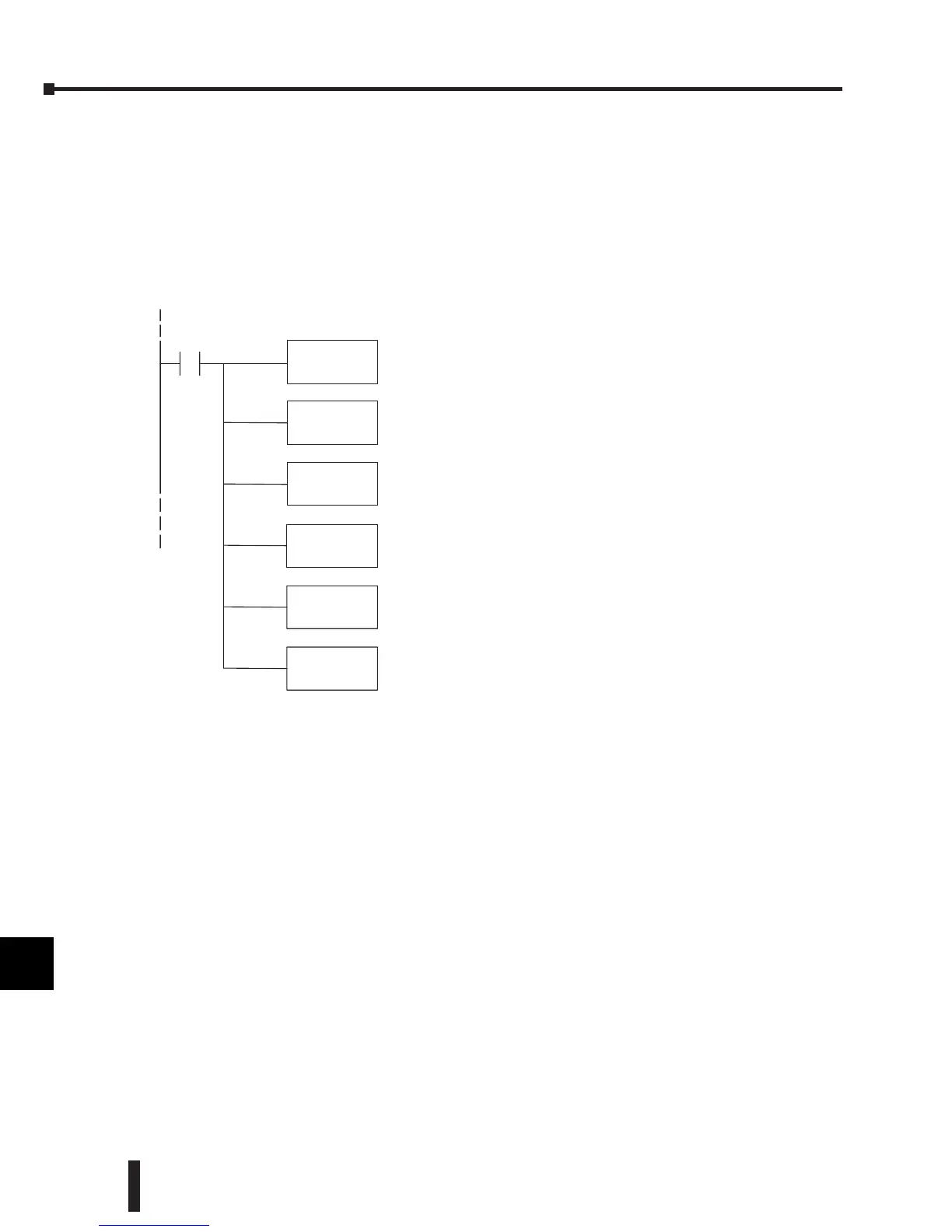
BTOR
Convertfrombinarytoreal data format.
MULR
R1400
Multiply by 1400;
EU range X10for implied decimal.
DIVR
R65535
Divide by 65535;
16 bit digitalrange.
(Use R16383 for14 bit;R4095for 12 bit.)
LD
V2000
SP1
Loadinput channel1digitalvalue intoaccumulato
 Loading...

