DL205 Analog Manual, 7th Edition Rev. D
16-19
Chapter 16: F2-8AD4DA-2, 8-Ch. In / 4-Ch. Out Analog Voltage Combination
1
2
3
4
5
6
7
8
9
10
11
12
13
14
15
16
C
D
1
2
3
4
5
6
7
8
9
10
11
12
13
14
15
16
C
D
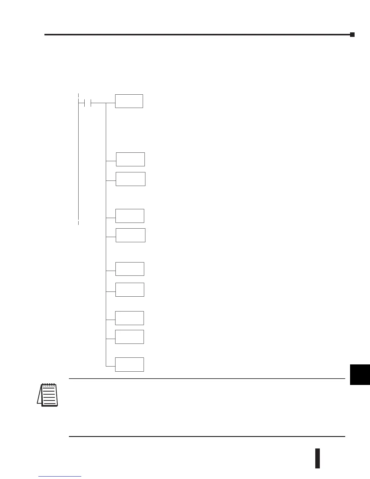
Module Configuration Example 3:
NOTE: Binary data format is recommended for 14 or 16 bit resolution input data, especially if the input
data is to be used in any math instructions (DL205 User Manual, ch.5). There is only one V-memory word
(16 bits) available for the actual data. Although the 12 bit resolution maximum value of 4095 can be stored
in one word using either binary or BCD formats, the 14 and 16 bit resolution maximum values of 16383 and
65535 both exceed the BCD format’s maximum single word capacity of 9999. Double word math would be
required for 14 or 16 bit data in BCD format. Binary data format is also useful for displaying data on some
operator interfaces.
LD
K
LDA
O2000
OUT
V7673
Loads aconstantthatspecifies the numberofchannelstoscan and
thedataformat. (See note below regarding dataformat. )(Theleading
zero in this LD instructionisshownfor clarity. It canbe entered by the
programmer, but it will be droppedbythe programming software.)
Theupper byte appliestothe inputs. Themostsignificant nibble
(MSN)selects the dataformat(0=BCD, 8=Binary), and theLSN
selects the number of channels(1, 2, 3, 4, 5, 6, 7, or 8) to scan.
Thelower byte appliestothe outputs. Themostsignificant nibble
(MSN)selects the dataformat(0=BCD, 8=Binary), and theLSN
selects the number of channels(1, 2, 3, or 4) to scan.
This constant designatesthe firstV-memorylocationthatwillbe
used to storethe inputdata.For example, theO2000 entered here
would mean: Ch1--V2000, V2001;Ch2 -- V2002, V2003; Ch3--
V2004,V2005; Ch4--V2006,V2007.For eachchannel,the 1stword
holds thedata, and the 2nd word is needed only when displaying 14
or 16 bit datainBCD format.The 2ndwordcontains themost
significant digitinthose cases.
Theconstant O2000isstored here. V7673isassigned to slot 3 and
acts as a pointer,whichmeansthe CPUwilluse thevalue in this
locationtodetermine exactlywheretostore theincomingdata.
OUT
V7663
Special V-memory location assignedtoslot3that contains the
numberofinput and output channels.
LDA
O2020
OUT
V7703
This constant designates thefirst V-memory locationthatwillbe
used forthe analog outputdata. Forexample,the O2020 entered
herewould mean:Ch1 -- V2020, V2021;Ch2 -- V2022,V2023. For
eachchannel,the 1stwordholds thedata, and the 2nd word is
needed only when displaying 14 or 16 bit datainBCD format.The
2nd word contains themos tsignificant digitinthosecases.
Theconstant O2020isstored here. V7703isassigned to slot 3 and
acts as a pointer,whichmeansthe CPUwilluse thevalue in this
location to determine exactlywhereto obtain the outputdata.
0402
LD
K0
Loads aconstantthatspecifies theresolutions for eachofthe input
channels. This constant is determinedbythe values of two bitsper
channel,asshown previously in “InputResolutions Selection Bits”.
Theconstant 0configures eachofthe eightinput channelsfor 12
bits.
OUT
V36403
SpecialV-- memory location assigned to slot 3that containsthe
resolution settings foreachofthe inputchannels.
LD
K5555
Loadsaconstant that specifiesthe track and hold settingsfor each
of theinputchannels. This constant is determinedbythe values of
twobits per channel,aspreviously shownin“Track and Hold
Selection Bits”. Theconstant 5555(hex)configures eachofthe eight
inputchannelstotrack and hold theminimum value.
OUT
V36423
SpecialV-- memory location assigned to slot 3that containsthe track
and holdsettingsfor eachofthe inputchannels..
Input Resolution = 12 bit,
Input/Output Range = 0–10V in, 0–10V out,
Input Track and Hold = all inputs maximum value.
Number of Channels = 4 in, 2 out,
Data Format = BCD in, BCD out,
 Loading...

