DL205 Analog Manual, 7th Edition Rev. D
13-9
Chapter 13: F2-02DAS-2, 0-5V, 0-10V, 2-Channel Isolated Analog Output
1
2
3
4
5
6
7
8
9
10
11
12
13
14
A
B
C
D
1
2
3
4
5
6
7
8
9
10
11
12
13
14
A
b
C
D
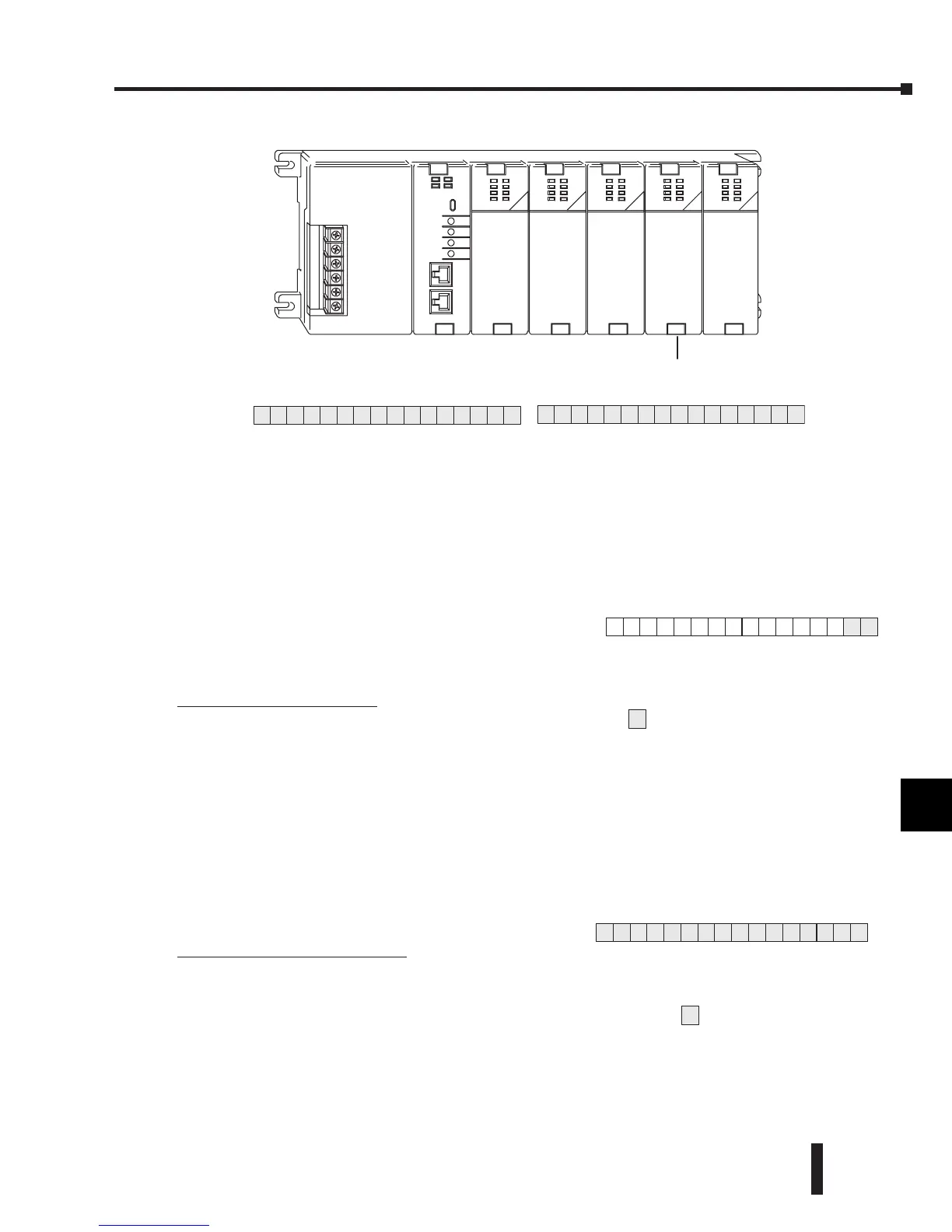
The individual bits in this data word location, represents specific information about the analog
signal.
Channel Select Outputs
Two of the outputs select the active channel.
Remember, the V-memory bits are mapped directly
to discrete outputs. Turning a bit OFF selects a
channel. By controlling these outputs, the channel
to be updated can be selected.
Y41 Y40 Channel
On Off 1
Off On 2
Off Off 1 & 2 (same data
to both channels)
On On None (both channels
hold current values)
Analog Data Bits
The first sixteen bits represent the analog data in
binary format.
Bit Value Bit Value
0 1 8 256
1 2 9 512
2 4 10 1024
3 8 11 2048
4 16 12 4096
5 32 13 8192
6 64 14 16384
7 128 15 32768
Y
2
0
Y
3
7
 Loading...


