DL205 Analog Manual, 7th Edition Rev. D
9-2
Chapter 9: F2-02DA-2, F2-02DA-2L, 2-Channel Analog Voltage Output
1
2
3
4
5
6
7
8
9
10
11
12
13
14
A
B
C
D
Module Specifications
The F2-02DA-2 and F2-02DA-2L Analog Output modules
provide several hardware features:
• Analog outputs are optically isolated from the PLC
logic.
• The modules have a removable terminal block so the
module can be easily removed or changed without
disconnecting the wiring.
• Both channels can be updated in one scan if either a DL240,
a DL250-1 or a DL260 CPU is used in the PLC.
• F2-02DA-2: Low-power CMOS design requires less than
60mA from an external 24VDC power supply.
• F2-02DA-2L: Low-power CMOS design requires less than
70mA from an external 12VDC power supply.
• Outputs can be independently configured for any of the
following ranges:
1) 0–5 VDC
2) 0–10 VDC
3) ±5VDC
4) ±10VDC
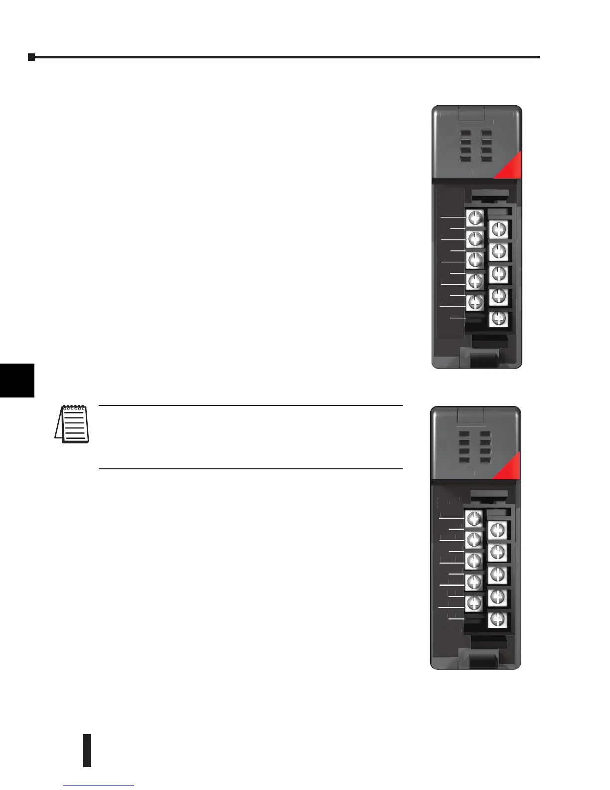
NOTE: The F2-02DA-2 and F2-02DA-2L modules look very similar and it is
very easy to mistake one module for the other. If the module being used does
not work, check the terminal label to see if it is a 12V (L) or a 24V model and
that it is being supplied with the proper input voltage.
Analog Output Configuration Requirements
The F2-02DA-2 (L) Analog output appears as a 16-point
discrete output module. The module can be installed in any
slot of a DL205 PLC, but the available power budget and
discrete I/O points are the limiting factors. Check the DL205
PLC User Manual for the particular model of CPU and I/O
base being used for information regarding power budget and
number of local, local expansion or remote I/O points.
1
2
3
4
5
6
7
8
9
10
11
12
13
14
A
b
C
D
+24V
CH1+
CH2+
NC
NC
0V
CH1–
CH2–
NC
NC
F2-02DA-2
OUTANALOG
2CH
F2-02DA-2
18-30VDC
60mA
ANALOG OUT
0-5VDC
-5-+5VDC
0-10VDC
-10-+10VDC
+
 Loading...

