DL205 Analog Manual, 7th Edition Rev. D
15-26
Chapter 15: F2-8AD4DA-1, 8-Ch. In / 4-Ch. Out Analog Current Combination
1
2
3
4
5
6
7
8
9
10
11
12
13
14
15
B
C
D
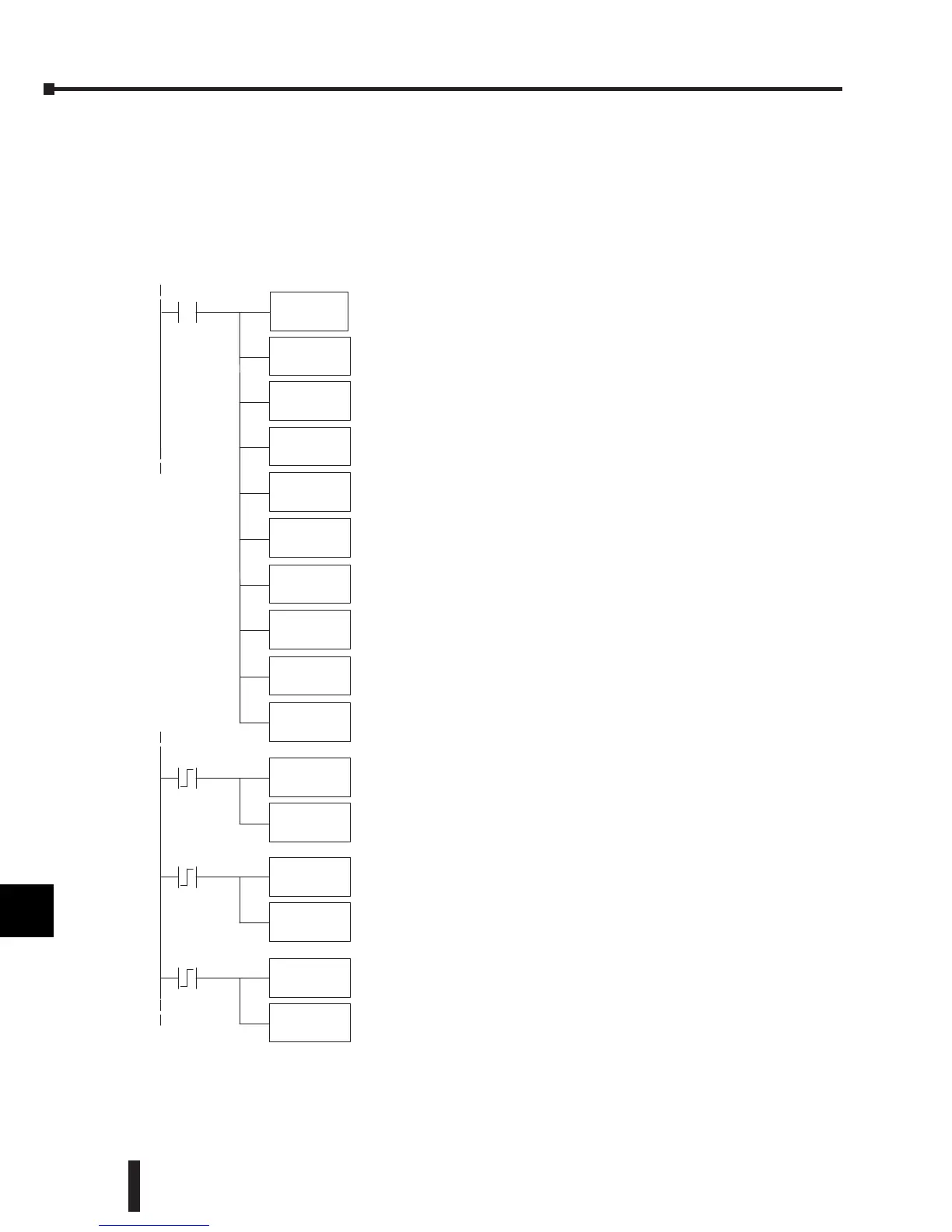
Track and Hold Example:
Number of Channels = 1 in, 1 out,
Data Format = binary in, binary out,
Input resolution = 16 bits,
Input Track and Hold = channel 1 reset.
1
2
3
4
5
6
7
8
9
10
11
12
13
14
15
b
C
D
SP0
LD
Rung 1, ModuleConfiguration:
Input: binarydataformat, 1channel.
Output:binary dataformat, 1channel.
Modulelocation: local base,slot 3.
Input data 1stmemory location: V2000
Output data1st memory location: V2020
Inputresolution: 16 bit channel1.
InputTrack and Hold: resetchannel1.
K8181
OUT
V7663
LDA
O2000
OUT
V7673
LDA
O2020
OUT
V7703
LD
K2
OUT
V36403
LD
K3
OUT
V36423
LD
K2
C1
OUT
V36423
LD
K3
OUT
V36423
C3
C5
LD
K1
OUT
V36423
C1 loadsvalue of 2(binary 10)intothe Trackand Hold Selection
register.Thisset sinput channel 1for Track and Hold Maximum
Value. As the analog value varies, onlyameasured value highertha
thepreviously stored value will be writtentoV2000.
C3 loadsavalue of 3(binary 11)intothe Track and Hold Selection
register.Thissetsinput channel1forTrack and Hold ResetValue.
Real-- time measured values will be writtentoV2000until another
Track and Hold Selection is made.
C5 loadsvalue of 1(binary 01) intothe Trackand Hold Selection
register.Thissetsinput channel1forTrack andHoldMinimum Va
 Loading...

