DL205 Analog Manual, 7th Edition Rev. D
2-14
Chapter 2: F2-04AD-1, F2-04AD-1L, 4-Channel Analog Current Input
1
2
3
4
5
6
7
8
9
10
11
12
13
14
A
B
C
D
1
2
3
4
5
6
7
8
9
10
11
12
13
14
A
b
C
D
Writing the Control Program
Reading Values: Pointer Method and Multiplexing
There are two methods which can be used to read values:
1. The pointer method
2. Multiplexing
The multiplexing method must be used when using a DL230 CPU. The multiplexing method
must also be used with remote I/O modules (the pointer method will not work). Either method
can be used with the DL240, DL250-1 and DL260 CPUs, but for ease of programming it is
strongly recommended to use the pointer method.
Pointer Method for the DL240, DL250-1, and DL260
The DL205 series has special V-memory locations assigned to each base slot that will greatly
simplify the programming requirements. These V-memory locations allow you to:
• specify the data format
• specify the number of channels to scan
• specify the storage locations
NOTE: DL250 CPUs with firmware release version 1.06 or later support this method. If the DL230 example needs to be
used, module placement in the base is very important. Review the section earlier in this chapter for guidelines.
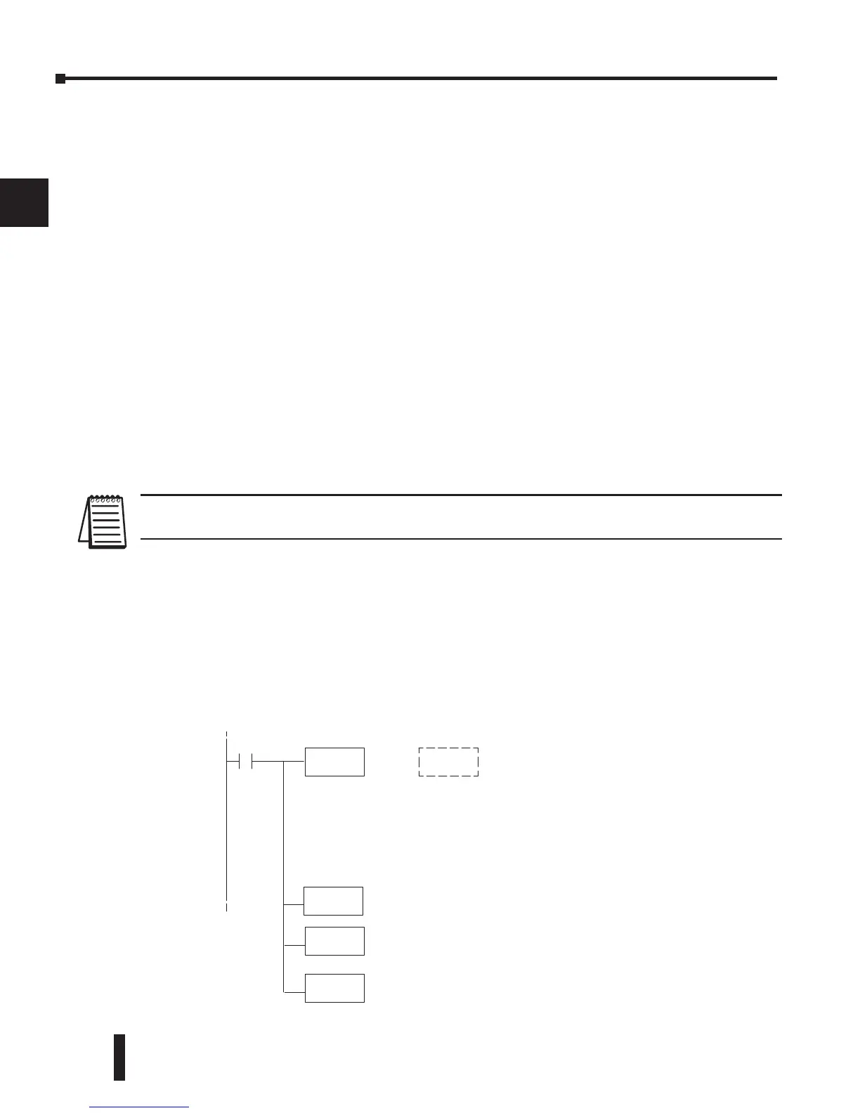
The example program shows how to setup these locations. Place this rung anywhere in the
ladder program, or in the initial stage if stage programming instructions are being used. This
is all that is required to read the data into V-memory locations. Once the data is in V-memory
math can be used on the data, compare the data against preset values, and so forth. V2000 is
used in the example but you can use any user V-memory location. In this example the module
is installed in slot 2. Be sure to use the V-memory locations for the module placement. The
pointer method automatically converts values to BCD (depending on the LD statement in the
ladder logic).
SP0
LD
K
LDA
O2000
OUT
V7672
This loads an octalvalue forthe firstV-memory location that will be
used to storethe incoming data.For example, theO2000 entered
herewould designate thefollowing addresses.
Ch1--V2000, Ch2--V2001,Ch3 -- V2002, Ch 4--V2003
Theoctal address (O2000) is stored here.V7672isassigned to slot
2 and acts as a pointer,which means theCPU will usethe octal
value in this location to determineexactly wheretostore the
incoming data.
OUT
V7662
SpecialV-memorylocationassigned to slot 2thatcontains the
numberofchannelsto scan.
00
LD
Loads aconstantthatspecifies thenumberofchannelsto scanand
thedataformat.The upper byte,mostsignificant nibble(MSN)
selects the dataformat(i.e. 0=BCD, 8=Binary),the LSNselec ts the
numberofchannels(i.e. 1, 2, 3, or 4).
-or-
Thebinary format is used for displaying dataonsomeoperator
interfaces.The DL230/240CPUsdo not supportbinarymath
functions, whereasthe DL250 does.
04 K0084
 Loading...

