DL205 Analog Manual, 7th Edition Rev. D
15-21
Chapter 15: F2-8AD4DA-1 8-Ch. In / 4-Ch. Out Analog Current Combination
1
2
3
4
5
6
7
8
9
10
11
12
13
14
15
B
C
D
1
2
3
4
5
6
7
8
9
10
11
12
13
14
15
b
C
D
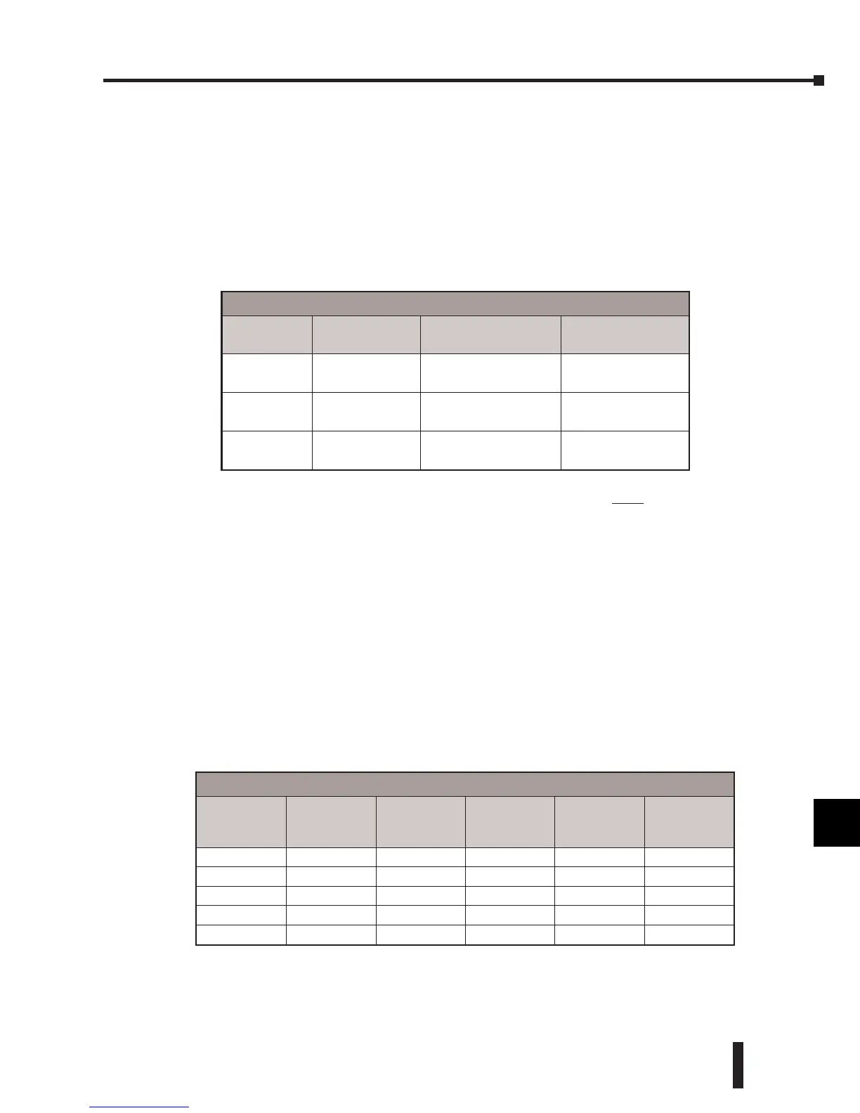
Analog and Digital Input Data Value Conversion
Sometimes it is useful to be able to quickly convert between the signal levels and the digital
values. This is especially helpful during machine startup or troubleshooting. The table provides
formulas to simplify the conversion.
Notice that the mathematical relationship between the analog and digital values remains the
same regardless of whether 4–20 mA or 0–20 mA transmitters are used. Only the engineering
unit input scaling will vary, as will be shown later.
Input Value Comparisons: Analog, Digital, Engineering Units
The following table shows how the input analog, digital, and engineering unit values are
related to each other. The above example is a measurement of pressure from 0.0–140.0 PSI,
using a multiplier of 10 for one implied decimal place.
Analog and Digital Input Data Conversion
Resolution X-mitter Range
If the digital value is
known
If the analog
signal is known
12 bit
0–4095
0–20 mA
4–20 mA
A = (D)(20) / 4095 D = (A)(4095) / 20
14 bit
0–16383
0–20 mA
4–20 mA
A = (D)(20) / 16383 D = (A)(16383) / 20
16 bit
0–65535
0–20 mA
4–20 mA
A = (D)(20) / 65535 D = (A)(65535) / 20
• A = Analog value from current transmitter
• A
max
= Maximum analog value
• D = Digital value of input provided to PLC CPU
• D
max
= Maximum digital value
A = (D)(A
max
) / (D
max
)
D = (A)(D
max
) / (A
max
)
D = (A)
65535
20
D = (12) (3276.75)
D = 39321
For example, if 16 bit resolution is being
used, and the signal measured is 12mA, the
formula can be easily used to determine the
digital value (D) that should be stored in the
V-memory location that contains the data.
Analog, Digital, and Engineering Units Input Comparisons
Analog (mA)
Digital
12 Bit
Digital
14 Bit
Digital
16 Bit
E.U.
0–20 mA
Transmitter
E.U.
4–20 mA
Transmitter
20 4095 16383 65535 1400 1400
12 2457 9830 39321 840 700
10 2048 8192 32768 700 525
4 819 3277 13107 280 0
0 0 0 0 0 N/A
 Loading...

