DL205 Analog Manual, 7th Edition Rev. D
10-6
Chapter 10: F2-08DA-1, 8-Channel Analog Current Output
1
2
3
4
5
6
7
8
9
10
11
12
13
14
A
b
C
D
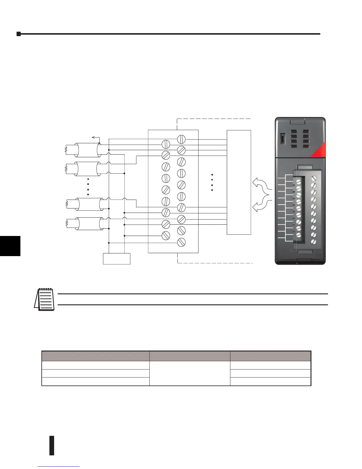
Wiring Diagram
The F2-08DA-1 module has a removable connector which helps to simplify wiring. Just
squeeze the top and bottom retaining clips and gently pull the connector from the module.
Use the following diagram to connect the field wiring. Channels 1 and 2 are shown wired for
sourcing, and channels 7 and 8 are shown wired for sinking. The diagram also shows how to
wire an optional loop power supply.
NOTE 1: Shields should be connected to the 0V terminal of the module.
Load Range
The maximum load resistance depends on the particular loop power supply being used.
1
2
3
4
5
6
7
8
9
10
11
12
13
14
A
b
C
D
OUT
F2-08DA-1
ANALOG
8 CHANNEL
18-26.4VDC
80mA
4-20mA
SNK-SRC
1-O
2-O
3-O
4-O
5-O
6-O
7-O
8-O
0V
1-I
2-I
3-I
4-I
5-I
6-I
7-I
8-I
N/C
24V
See
NOTE 1
Typical User Wiring
SOURCE
Configurations
SINK
Configurations
Ch 1 load
250 ohms
typical
Ch 2 load
250 ohms
typical
Ch 7 load
250 ohms
typical
Ch 8 load
250 ohms
typical
18-30 VDC
+
–
Internal
Module
Wiring
Sink/Source
Circuitry
1–O
2–O
3–O
4–O
5–O
6–O
7–O
8–O
0V
1–I
2–I
3–I
4–I
5–I
6–I
7–I
8–I
N/C
24V
Loop Power Supply Voltage Source Load Range Sink Load Range
30VDC
0 – 400q
0 – 1200q
24VDC
0 – 900q
18VDC
0 – 600q
 Loading...

