DL205 Analog Manual, 7th Edition Rev. D
14-8
Chapter 14: F2-4AD2DA, 4-Ch. In / 2-Ch. Out Analog Combination
1
2
3
4
5
6
7
8
9
10
11
12
13
14
A
B
C
D
1
2
3
4
5
6
7
8
9
10
11
12
13
14
A
b
C
D
Module Operation
Before beginning to write the control program, it is important to take a few minutes to under-
stand how the module processes the analog signals.
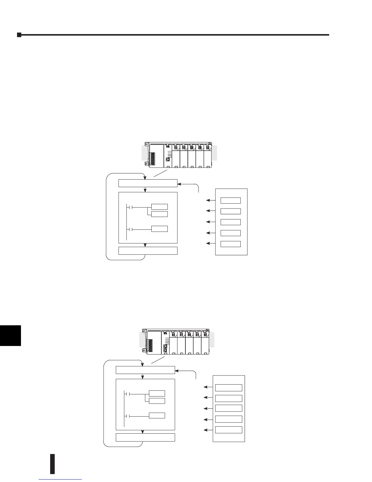
Input Channel Scanning Sequence for a DL230 CPU (Multiplexing)
The F2-4AD2DA module can supply different amounts of data per scan, depending on the
type of CPU being used. The DL230 can obtain one channel of input data per CPU scan.
Since there are four channels, it can take up to four scans to get the data for all channels. Once
all channels have been scanned the process starts over with channel 1. Unused channels are not
processed, so if only two channels are selected, each channel will be updated every other scan.
Input Channel Scanning Sequence for DL240, DL250-1, and DL260 CPUs
(pointer method)
If a DL240, a DL250-1 or a DL260 CPU is being used, the input data for all four channels
can be obtained in one scan. This is because the DL240/250-1/260 CPUs supports special
V-memory locations that are used to manage the data transfer. This is discussed in more detail
in the section on Writing the Control Program.
Channel1
Scan NRead the data
Store data
Channel2
Scan N+1
Channel3
Scan N+2
Channel4Scan N+3
Channel1
Scan N+4
Scan
System With
DL230 CPU
Read Inputs
ExecuteApplicationProgram
WritetoOutputs
Ch1, 2, 3, 4
Scan NRead the data
Store data
Read Inputs
ExecuteApplicationProgram
Ch 1, 2, 3, 4
Scan N+1
Scan N+2
Scan N+3
Scan N+4
Scan
WritetoOutputs
Ch1, 2, 3, 4
Ch 1, 2, 3, 4
Ch 1, 2, 3, 4
System With
DL240/250-- 1/260
CPU
 Loading...

