DL205 Analog Manual, 7th Edition Rev. D
13-4
Chapter 13: F2-02DAS-2, 0-5V, 0-10V, 2-Channel Isolated Analog Output
1
2
3
4
5
6
7
8
9
10
11
12
13
14
A
B
C
D
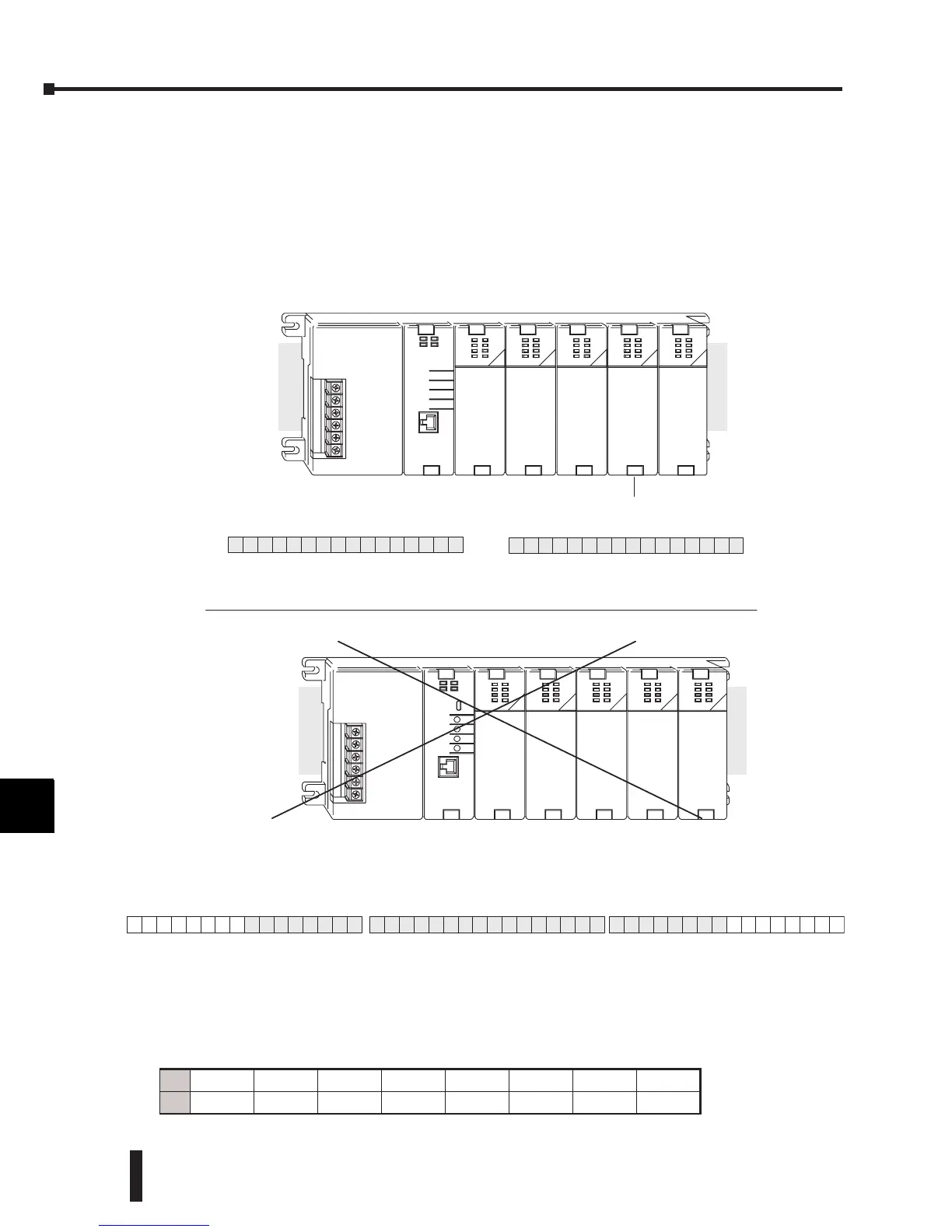
Special Placement Requirements (DL230 and Remote I/O Bases)
It is important to examine the configuration if a DL230 CPU is being used in a multiplexing
program. As can be seen in the section on Writing the Control Program, V-memory locations
are used to capture the analog data. If the module is placed in a slot so that the output points
do not start on a V-memory boundary, the program instructions will not be able to access the
data. This also applies when placing this module in a remote base using a D2-RSSS in the
CPU slot.
To use the V-memory references required for a DL230 CPU, the first output address assigned
to the module must be one of the following Y locations. The table also shows the V-memory
addresses that correspond to these Y locations.
1
2
3
4
5
6
7
8
9
10
11
12
13
14
A
b
C
D
Y
3
7
V40501
BSL
BSM
Y
2
0
V40500V40503
Correct!
16pt
Input
8pt
Input
32pt
Output Output
8pt16pt
Output
X0
--
X17
X20
--
X27
Y0
--
Y17
Y20
--
Y57
Y60
--
Y67
Slot 0Slot1 Slot 2Slot3 Slot 4
Y
2
7
Y
3
0
V40501 -- V40502
Y
5
7
V40502
MSB
Y
4
0
Y
4
7
Y
5
0
LSB
16pt
Input
8pt
Input
8pt
Output Output
32pt16pt
Output
X0
--
X17
X20
--
X27
Y0
--
Y17
Y20
--
Y27
Y30
--
Y67
F2-02DAS-- 2
Y
4
Y
Y0 Y20 Y40 Y60 Y100 Y120 Y140 Y160
V
V40500 V40501 V40502 V40503 V40504 V40505 V40506 V40507
Data is split over three locations, so instructions cannot access data
from a DL230 (or when module is placed in a remote base).
 Loading...

