DL205 Analog Manual, 7th Edition Rev. D
11-11
Chapter 11: F2-08DA-2, 8-Channel Analog Voltage Output
1
2
3
4
5
6
7
8
9
10
11
12
13
14
A
B
C
D
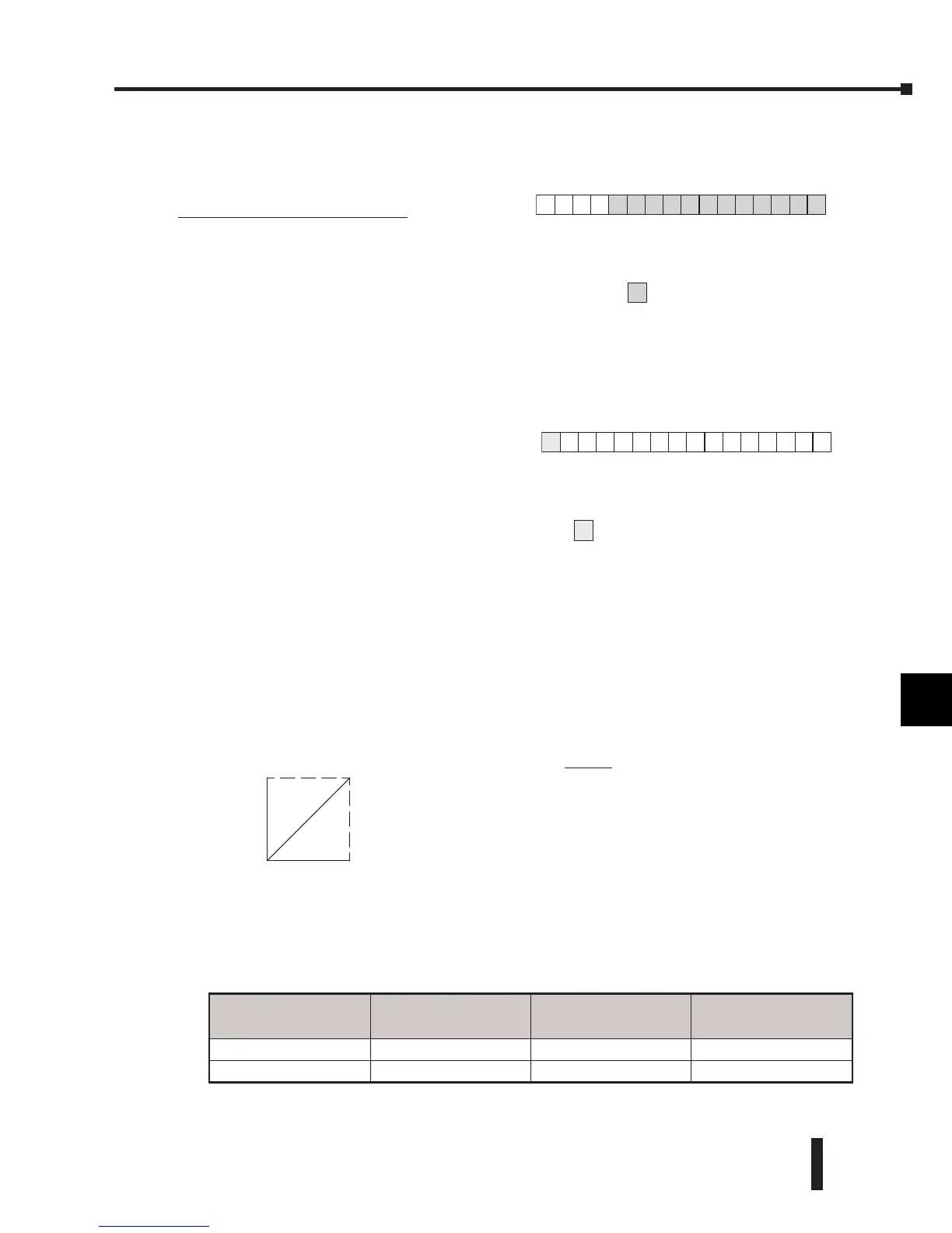
Analog Data Bits
The first twelve bits represent the analog
data in binary format.
Bit Value Bit Value
0 1 6 64
1 2 7 128
2 4 8 256
3 8 9 512
4 16 10 1024
5 32 11 2048
Output Enable
The last output can be used to update
outputs. If this output is OFF, the outputs
are cleared.
Module Resolution
Since the module has 12-bit resolution, the analog signal is converted into 4096 counts
ranging from 0–4095 (2
12
). For example, for a 0–10V range, send a 0 to get a 0V signal, and
4095 to get a 10V signal. This is equivalent to a binary value of 0000 0000 0000 to 1111 1111
1111, or 000 to FFF hexadecimal.
Each count can also be expressed in terms of the signal level by using the equation shown.
The table below shows the smallest change in signal level due to a digital value change of 1
LSB count.
1
2
3
4
5
6
7
8
9
10
11
12
13
14
A
b
C
D
BSLBSM
Y
2
0
10V
0V
0 4095
0-- 10V
Voltage Range Signal Span Divide By
Smallest Output
Change
0–5V 5 volts 4095 1.22 mV
0–10V 10 volts 4095 2.44 mV
Resolution =
H – L
4095
H = High limit of the signal range
L = Low limit of the signal range
 Loading...

