DL205 Analog Manual, 7th Edition Rev. D
2-9
Chapter 2: F2-04AD-1, F2-04AD-1L, 4-Channel Analog Current Input
1
2
3
4
5
6
7
8
9
10
11
12
13
14
A
b
C
D
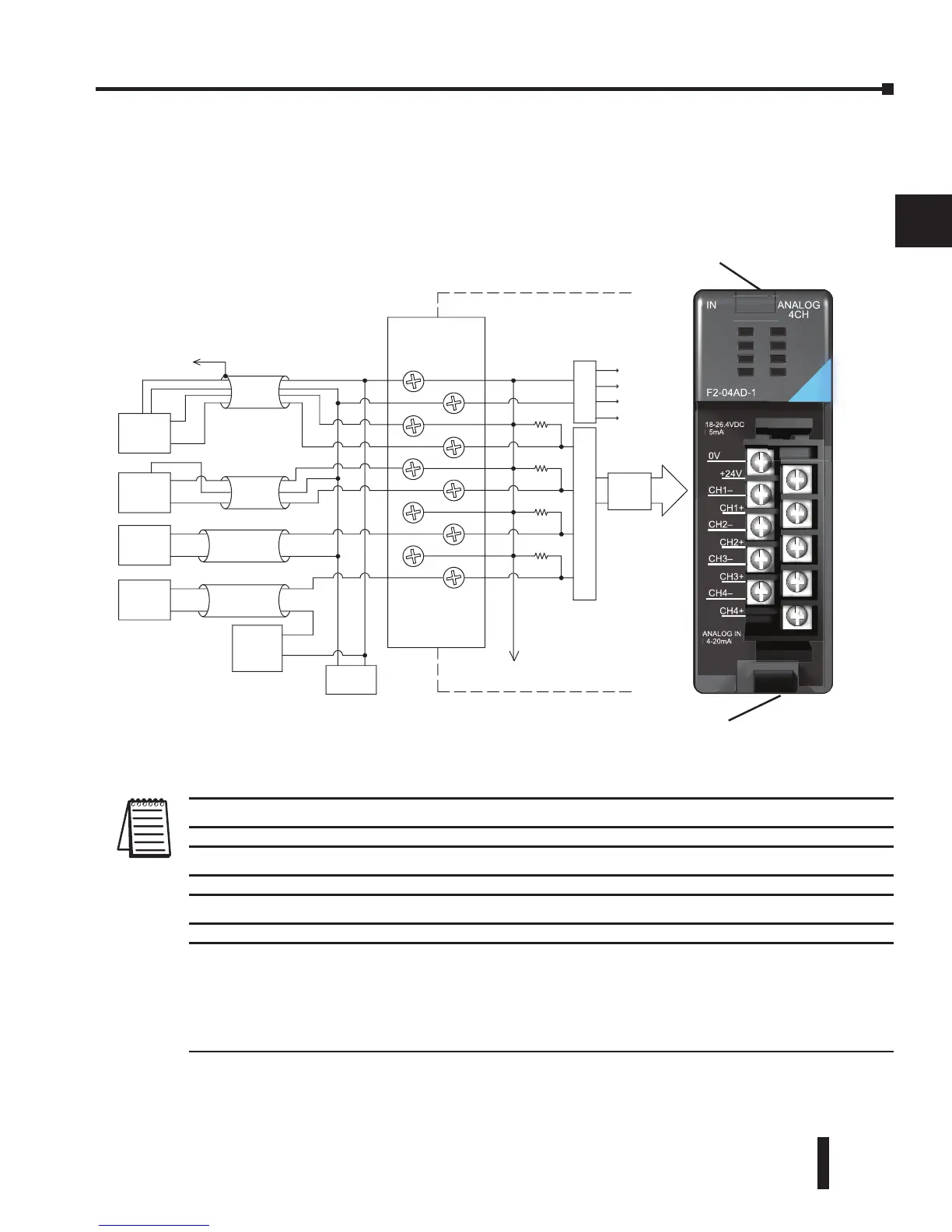
Wiring Diagram
The F2-04AD-1, module has a removable connector to simplify wiring the module. Just
squeeze the top and bottom retaining clips and gently pull the connector from the module.
Use the following diagram to connect the fi eld wiring
NOTE 1: Shields should be grounded at the signal source.
NOTE 2: More than one external power supply can be used, provided all the power supply commons are connected.
NOTE 3: A Series 217, 0.032A fast-acting fuse is recommended for 4–20 mA current loops.
NOTE 4: If the power supply common of an external power supply is not connected to 0 VDC on the module, then the
output of the external transmitter must be isolated. To avoid ”ground loop” errors, recommended 4–20 mA transmitter
types are:
2 or 3 wire: Isolation between input signal and power supply.
4 wire: Isolation between input signal, power supply, and 4–20 mA output.
2
3
4
5
6
7
8
9
10
11
12
13
14
A
b
C
D
Retaining clip
Retaining clip
Analog Switch
+
-
+
-
+
-
+
-
+
-
- +
+
+
-
DC to DC
Converter
+24V
CH1+
CH2+
CH3+
CH4+
0V
CH1–
CH2–
CH3–
CH4–
F2-04AD-1
IN ANALOG
4CH
18-26.4VDC
5mA
ANALOG IN
4-20mA
 Loading...

