DL205 Analog Manual, 7th Edition Rev. D
3-19
Chapter 3: F2-04AD-2, F2-04AD-2L, 4-Channel Analog Voltage Input
1
2
3
4
5
6
7
8
9
10
11
12
13
14
A
B
C
D
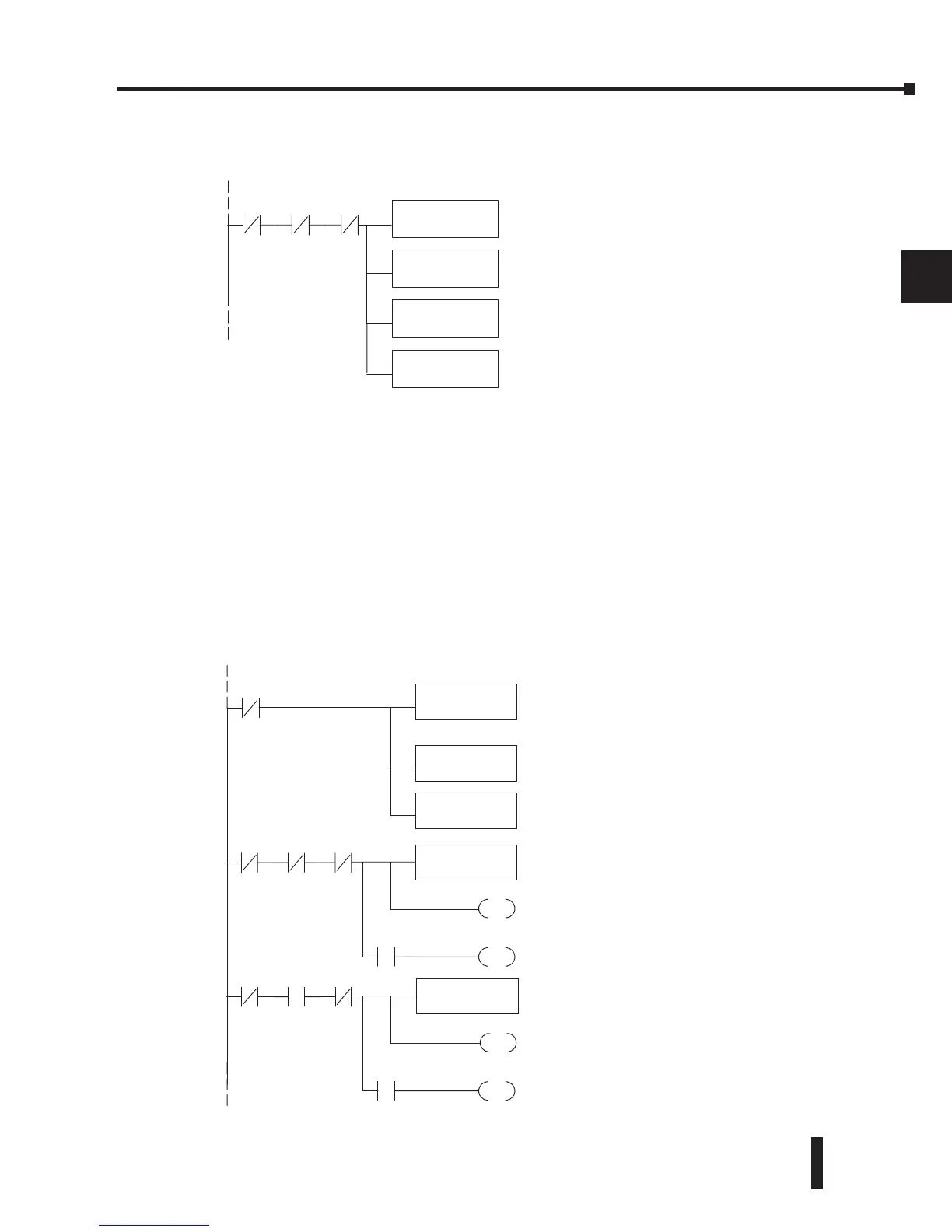
Single Channel Selected
The single channel program makes it easy to determine which channel has been selected.
Using Bipolar Ranges (Multiplexing)
Some additional logic is needed with bipolar ranges to determine whether the value being
returned represents a positive voltage or a negative voltage. For example, the direction of a
motor may be needed to be known. Since the DL230 only reads one channel per scan, the last
input can be used to show the sign (X37 in the examples).
The following program shows how to accomplish this. Since a negative value is always needed
to be known, these rungs should be placed before any other operations that use the data, such
as math instructions, scaling operations, and so forth. Also, if stage programming instructions
are being used, place these rungs in a stage that is always active. Please note, this logic is only
needed for each channel that is using bipolar input signals. The following example only shows
two channels but the rungs can be repeated for all four channels if needed.
1
2
3
4
5
6
7
8
9
10
11
12
13
14
A
b
C
D
It is usually easier to perform math operationsinBCD,
so it is besttoconvert the datatoBCD immediately.
Youcan leave out this instruction if your application
does notrequire it.
This instruction masksthe channelidentification bits.
Without this,the values used will not be correct, so do
not forget to include it.
Loadsthe complete datawordintothe accumulator.
TheV-memorylocation depends on theI/O
configuration. SeeAppendix Afor thememorymap.
X36 X34 X35
It is usually easier to perform math operationsin
BCD, so it is besttoconvert thedatatoBCD
immediately. Youcan leave out this instructionif
your application does not require it.
This instructionmasks thechannel identification
bits. Without this,the values used will not be
correct,sodo not forget to include it.
Loadsthe complete datawordintothe
accumulator. TheV-memorylocation depends
on the I/O configuration. SeeAppendixAfor
thememorymap.
LD
V40401
ANDD
KFFF
BCD
X36
X36 X34 X35
StoreChannel 1
OUT
V2000
When themoduleisnot busyand X34 and X35
areoff,channel 1 dataisstoredinV2000. C0 is
resettoindicatechannelone’s valueispositive.
SET
C0
X37
RST
C0
If X37is on, then thedatavalue representsa
negative voltage.C0isset to indicate channel1’s
value is negative.
X36 X34 X35
StoreChannel 2
OUT
V2001
When themoduleisnot busy, andX34 is on
and X35isoff,channel2dataisstoredin
V2001. C1 is resettoindic atethat channel2’s
value is positive.
SET
C1
X37
RST
C1
If X37is on, then thedatavalue represents a
negative voltage.C1isset to indicate that
 Loading...

