DL205 Analog Manual, 7th Edition Rev. D
13-8
Chapter 13: F2-02DAS-2, 0-5V, 0-10V, 2-Channel Isolated Analog Output
1
2
3
4
5
6
7
8
9
10
11
12
13
14
A
B
C
D
1
2
3
4
5
6
7
8
9
10
11
12
13
14
A
b
C
D
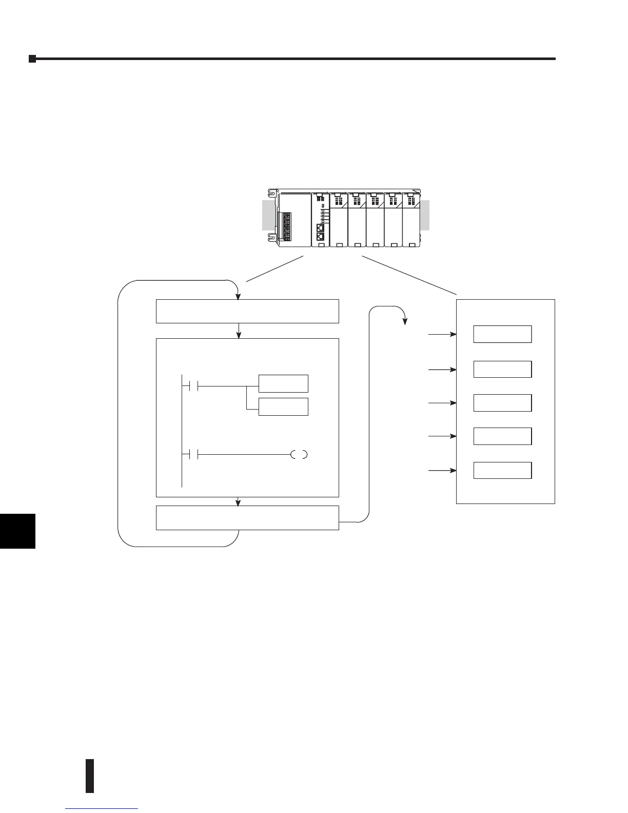
Channel Update Sequence for DL240, DL250-1, and DL260 CPUs
(Pointer Method)
If either a DL240, DL250-1 or DL260 CPU is used with the pointer method, all channels can
be updated on every scan. This is because the three CPUs support special V-memory locations
that are used to manage the data transfer. This is discussed in more detail in the next section
on Writing the Control Program.
Understanding the Output Assignments
Remember that the F2-02DAS-2 module appears to the CPU as a 32-point discrete output
module. These points provide the data value and an indication of which channel to update.
Note, if either a DL240, DL250 or DL260 CPU is being used, these bits may never have to
be used, but it may be an aid to help understand the data format.
Since all output points are automatically mapped into V-memory, the location of the data
word that will be assigned to the module can simply be determined.
Channel1,2
Channel1,2
Channel1,2
Channel1,2
Channel1,2
Scan N
Calculatethe data
Writedata
Read inputs
ExecuteApplic ationProgram
Scan N+1
Scan N+2
Scan N+3
Scan N+4
Scan
Writeto outputs
System With
DL240/250-- 1/260
CPU
 Loading...

