DL205 Analog Manual, 7th Edition Rev. D
7-15
Chapter 7: F2-04THM, 4-Channel Thermocouple Input
1
2
3
4
5
6
7
8
9
10
11
12
13
14
15
B
C
D
Negative Temperature Readings with Magnitude Plus Sign for the DL240, DL250-1
and DL260 CPUs (Pointer Method)
With bipolar ranges, some additional logic will be needed to determine whether the value
being returned represents a positive voltage or a negative voltage. For example, the direction
for a motor might need to be known. There is a solution for this:
• If bipolar ranges are used and a value greater than or equal to 8000
hex
is obtained, the value is
negative.
• If a value less than or equal to 7FFF
hex
is obtained, then the value is positive.
The sign bit is the most significant bit, which combines 8000
hex
to the data value. If the value
is greater than or equal to 8000
hex
, only the most significant bit and the active channel bits
need to be masked to determine the actual data value.
NOTE: DL240 CPUs with firmware release version 2.5 or later and DL250 CPUs with firmware release version 1.06 or
later support this method. Use the DL230 multiplexing example if your firmware is an earlier version.
The following two programs on this page and the next page show how this can be
accomplished. The first example uses magnitude plus sign (binary) and the second example
uses magnitude plus sign (BCD). The examples only show two channels.
It is good to know when a value is negative, so these rungs should be placed before any other
operations that use the data, such as math instructions, scaling operations, etc. Also, if stage
programming instructions are being used, these rungs should be in a stage that is always
active.
NOTE: This logic is only needed for each channel that is using bipolar input signals.
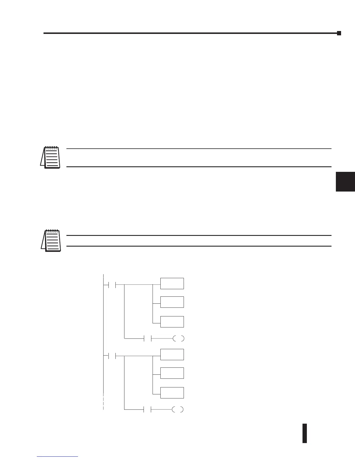
Magnitude Plus Sign (Binary)
1
2
3
4
5
6
7
8
9
10
11
12
13
14
15
b
C
D
SP1
OUT
C1
LD
V2000
OUT
V2010
Load channel 1datafromV-memoryintothe
accumulator.Contact SP1 is always on.
Putthe actual signal value in V2010. Nowyou canuse
thedatanormally.
ANDD
K7FFF
This instruction masksthe sign bitofthe binary data, if
it is set. Withoutthisstep, negativevalueswill not be
correct so do notforget to include it.
V2000 K8000
Channel 1datais negativewhenC1ison(avalue of
-- 1.0reads as 8010,--2.0 is 8020,etc.).
SP1
OUT
C2
LD
V2002
OUT
V2012
Load channel 2fromV-memoryintothe accumulator.
Contact SP1 is always on.
Putthe actual signal value in V2012. Nowyou canuse
thedatanormally.
ANDD
K7FFF
This instruction masksthe sign bitofthe binary data, if
it is set. Withoutthisstep, negativevalueswill not be
correct so do notforget to include it.
V2002 K8000
Channel 2datais negativewhenC2ison(avalue of
-- 1.0reads as 8010,--2.0 is 8020,etc.).
²
 Loading...

