DL205 Analog Manual, 7th Edition Rev. D
12-6
Chapter 12: F2-02DAS-1, 4-20mA Isolated 2-Channel Analog Current Output
1
2
3
4
5
6
7
8
9
10
11
12
13
14
A
b
C
D
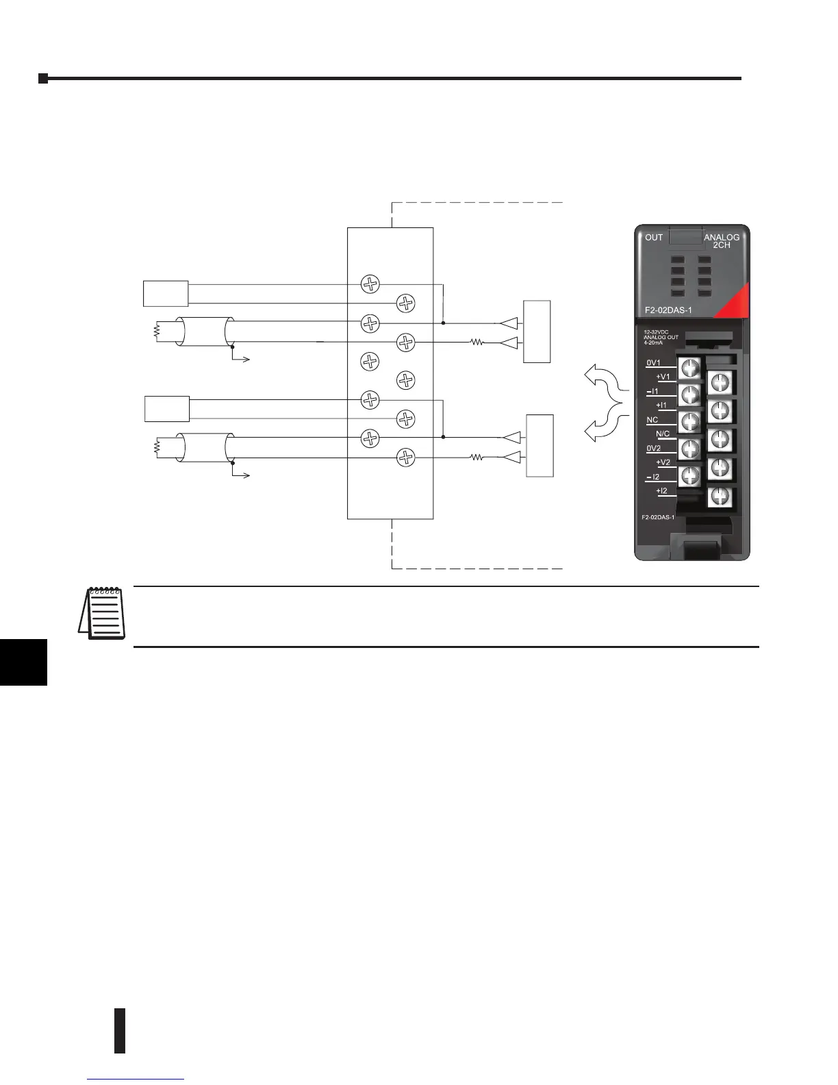
Wiring Diagram
The F2-02DAS-1 module has a removable connector which helps to simplify wiring. Squeeze
the top and bottom retaining clips and gently pull the connector from the module. Use the
following diagram to connect the fi eld wiring.
NOTE 1: Shields should be connected to the 0V terminal of the module or 0V of the power supply.
NOTE 2: Loads must be within the compliance voltage.
NOTE 3: For non-isolated outputs, connect all 0Vs together (0V1...0V2) and connect all +Vs together (+V1...+V2).
1
2
3
4
5
6
7
8
9
10
11
12
13
14
A
b
C
D
Internal module
wiring
+
--
Transmitter
See
0V1
+V1
0V2
--I2
+I2
+V2
NOTE 1
--I1
N/C
+I1
N/C
C
h 1
Max Load
Impedance
525 ohms
See
NOTE2
Supply
18--32VDC
See
NOTE 1
D/A
4--20mAcurrentsourcing
D/A
4--20mAcurrentsourcing
100ohms
100ohms
NOTE 3
See
+
--
Transmitter
Supply
18--32VDC
+V1
+I1
N/C
+V2
+I2
0V1
–I1
NC
0V2
– I2
F2-02DAS-1
OUT ANALOG
2CH
F2-02DAS-1
12-32VDC
ANALOG OUT
4-20mA
 Loading...

