DL205 Analog Manual, 7th Edition Rev. D
3-9
Chapter 3: F2-04AD-2, F2-04AD-2L, 4-Channel Analog Voltage Input
1
2
3
4
5
6
7
8
9
10
11
12
13
14
A
b
C
D
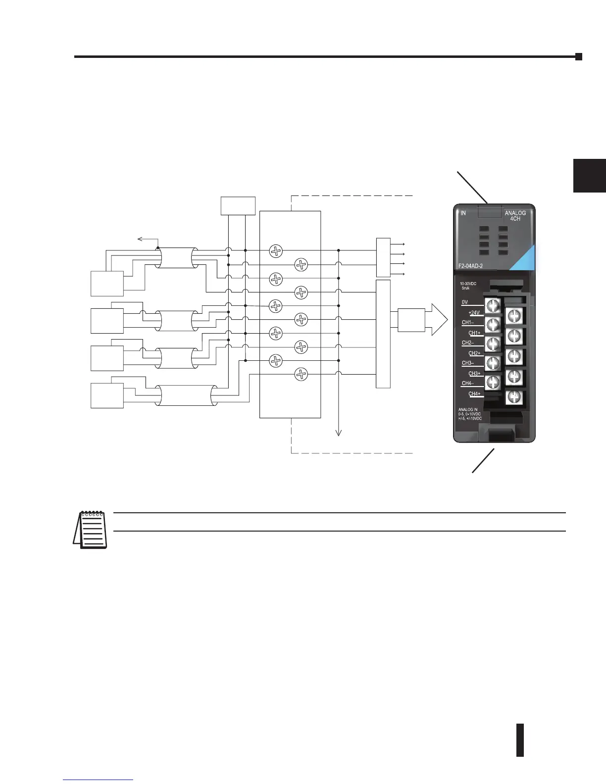
Wiring Diagram
The module has a removable connector to simplify wiring the module. Just squeeze the top
and bottom retaining clips and gently pull the connector from the module. Use the following
diagram to connect the fi eld wiring
NOTE: 1. Shields should be grounded at the signal source.
1
2
3
4
5
6
7
8
9
10
11
12
13
14
A
b
C
D
+ -
+24V
CH1+
CH2+
CH3+
CH4+
0V
CH1–
CH2–
CH3–
CH4–
F2-04AD-2
IN ANALOG
4CH
10-30VDC
5mA
ANALOG IN
0-5, 0 - 10VDC
+/-5, +/-10VDC
 Loading...

