DL205 Analog Manual, 7th Edition Rev. D
11-7
Chapter 11: F2-08DA-2, 8-Channel Analog Voltage Output
1
2
3
4
5
6
7
8
9
10
11
12
13
14
A
b
C
D
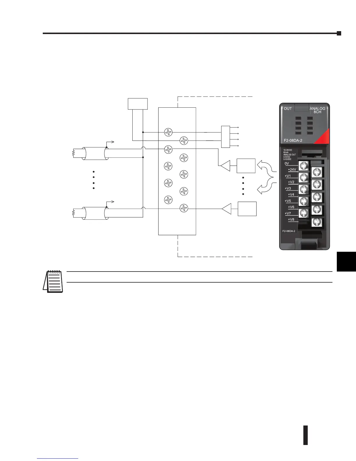
Wiring Diagram
The F2-08DA-2 module has a removable connector which helps to simplify wiring. Squeeze
the top and bottom retaining clips and gently pull the connector from the module. Use the
following diagram to connect the field wiring.
NOTE 1: Shields should be connected to the 0V terminal of the module or 0V of the power supply.
Internal
Module
Wiring
+ --
18--30VDC
S ee
0VDC
+24 VDC
+V5
+V7
+V8
NOTE 1
+V1
+V3
+V2
+V4
Voltage s ource
Ch 1
Ch 1 load
1K--10K ohms
minimum
Voltage s ource
Ch 8
DC to DC
Converter
+5V
+15V
0V
--15V
D to A
Converter
D to A
Converter
+V6
S ee
NOTE 1
Ch 8 load
1K--10K ohms
minimum
@ 90mA
+24V
+V2
+V4
+V6
+V8
0V
+V1
+V3
+V5
+V7
F2-08DA-2
OUT ANALOG
8CH
F2-08DA-2
18-30VDC
80mA
ANALOG OUT
0-5VDC
0-10VDC
 Loading...

