DL205 Analog Manual, 7th Edition Rev. D
14-18
Chapter 14: F2-4AD2DA, 4-Ch. In / 2-Ch. Out Analog Combination
1
2
3
4
5
6
7
8
9
10
11
12
13
14
A
B
C
D
1
2
3
4
5
6
7
8
9
10
11
12
13
14
A
b
C
D
Read Input Values (Multiplexing)
The DL230 CPU does not use special V-memory locations for transferring data. Since all
channels are multiplexed into a single data word, the control program must be setup to
determine which channel is being read. Since the module appears as X input points to the
CPU, simply use the active channel status bits to determine which channel is being read.
Note, this example is for a module installed in slot 3, as shown in the previous examples. The
addresses used would be different if the module was used in a different slot. These rungs can
be placed anywhere in the program or if stage programming is being used, place them in a
stage that is always active.
This multiplexing example can be used with all of the DL205 CPUs.
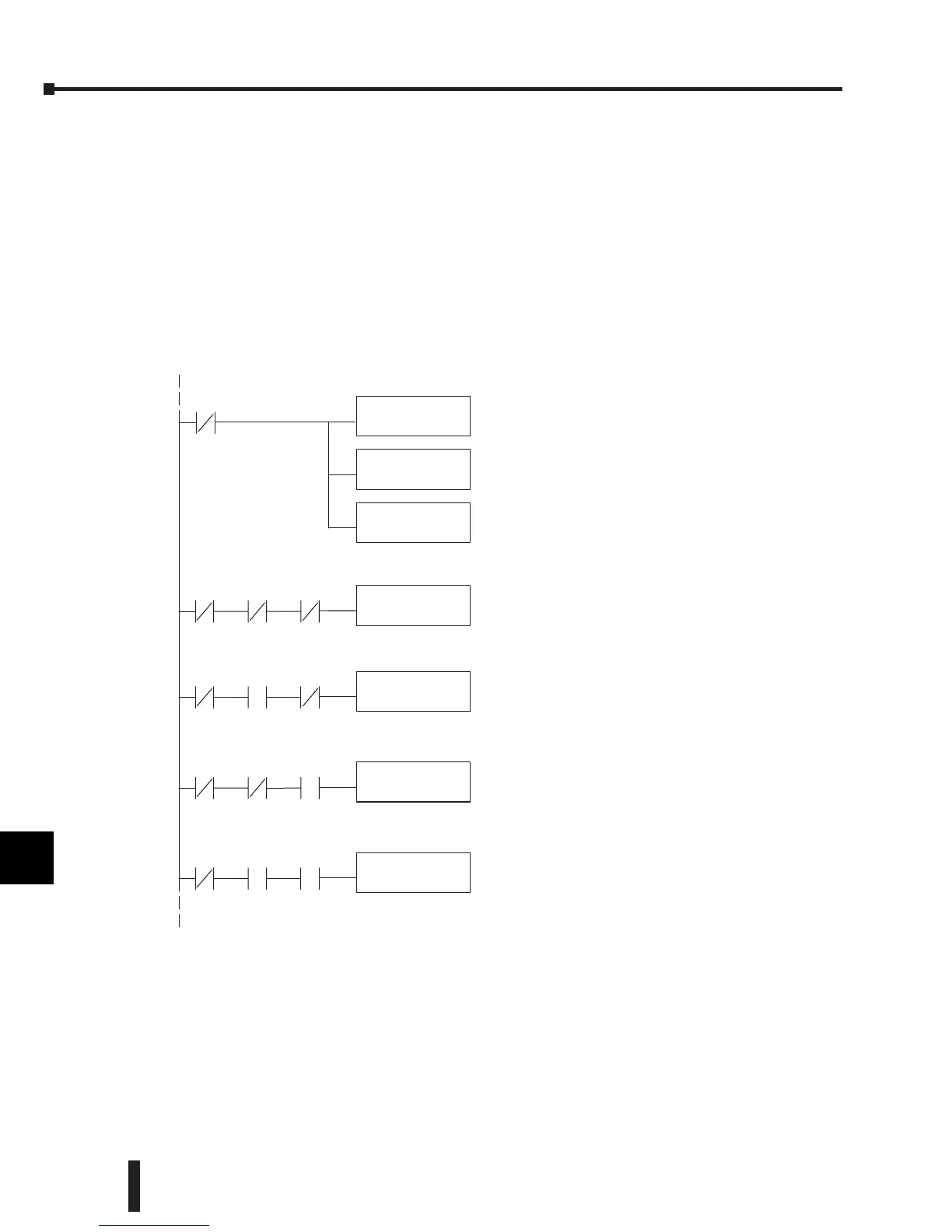
It is usually easier to perform math operationsin
BCD, Youcan leave out this instructionifyour
applicatio ndoes not require it.
This instruction masksthe channel identification bits.
Without this,the values used will not be correct so do
not forget to include it .
Loadsthe complete datawordintothe accumulator.
TheV-memorylocation depends on theI/O
configuration.See Appendix Afor thememorymap.
LD
V40401
ANDD
KFFF
BCD
X36
X36 X34 X35
StoreChannel 1
OUT
V2000
When themoduleis not busyand X36, X34and X35
areoff,channel 1dataisstoredinV2000.
When themoduleis not busyand X34ison and X35
and X36are off, channel2dataisstoredinV2001 .
When themoduleis not busyand X34 and X36are
off and X35ison, channel3data is stored in V2002.
When themoduleis not busyand both X34and X35are
on and X36isoff,channel4data is stored in V2003.
X36 X34 X35
StoreChannel 2
OUT
V2001
X36 X34 X35
StoreChannel 3
OUT
V2002
X36 X34 X35
StoreChannel 4
OUT
V2003
 Loading...

