DL205 Analog Manual, 7th Edition Rev. D
15-8
Chapter 15: F2-8AD4DA-1, 8-Ch. In / 4-Ch. Out Analog Current Combination
1
2
3
4
5
6
7
8
9
10
11
12
13
14
15
b
C
D
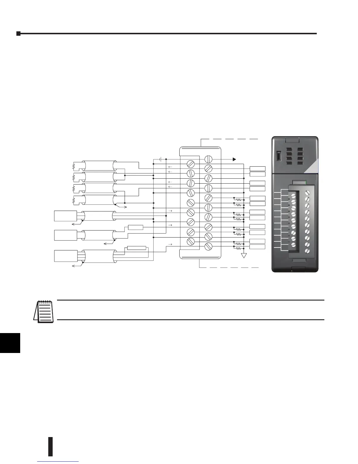
Wiring Diagram
The F2-8AD4DA-1 module has a removable connector to simplify wiring. Simply squeeze
the top and bottom retaining clips and gently pull the connector from the module. Use the
following diagram to connect the field wiring.
The diagram shows one power supply for both the module and the I/O signal loops. If a
separate module and loop supplies are to be used, connect the power supply 0V commons
together.
NOTE 1: Shields should be connected at their respective signal source.
NOTE 2: A series 217, 0.032A, fast-acting fuse is recommended for 4–20 mA current input loops.
1
2
3
4
5
6
7
8
9
10
11
12
13
14
15
b
C
D
shield, Channel 3
CH1 ADC
CH2 ADC
CH4 ADC
CH3 ADC
CH6 ADC
AC or DC
4--20mA transmitter
shield, Channel 8
transmitter
4--wire 4--20mA
See Note 2
CH8 ADC
I8+
100Ω
100Ω
CH7 ADC
COM
0.032A
4--20mA transmitter
shield, Channel 5
transmitter
2--wire 4--20mA
I5+
Isolated analog
circuit common
4--20mA transmitter
transmitter
3--wire 4--20mA
COM
+
100Ω
I3+
100Ω
100Ω
100Ω
CH5 ADC
COM
100Ω
100Ω
CH1 DAC
CH2 DAC
COM
CH4 DAC
CH3 DAC
Isolated analog
circ uit power
User 24VDC
supply
COM
24VDC+
0VDC--
I1+
I2+
I3+
I4+
4--20mA output
Channel 2
--
4--20mA output
Channel 3
--
4--20mA output
Channel 4
--
4--20mA output
Channel 1
--
See Note 2
Internal module wiring
Transmitter power
See Note 1
+
+
+
+
See Note 2
See Note 2
IN/
OUT
F2-8AD4DA-1
ANALOG
0V
OUT2
OUT3
0V
IN2
IN3
0V
IN6
IN7
24V
OUT1
0V
OUT4
IN1
0V
IN4
IN5
0V
IN8
18-26.4VDC 100mA
8 INPUTS
0-20mA
4 OUTPUTS
4-20mA
 Loading...

