DL205 Analog Manual, 7th Edition Rev. D
14-7
Chapter 14: F2-4AD2DA 4-Ch. In / 2-Ch. Out Analog Combination
1
2
3
4
5
6
7
8
9
10
11
12
13
14
A
b
C
D
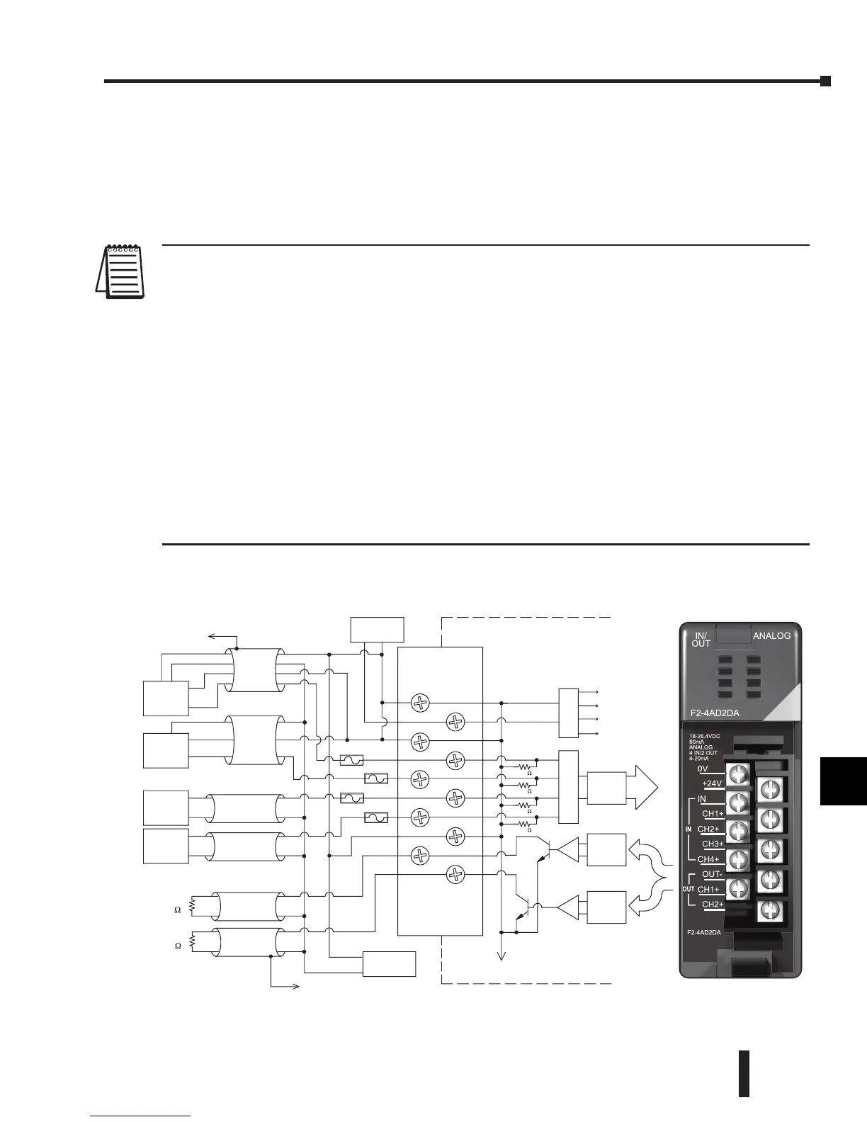
Wiring Diagram
The F2-4AD2DA module has a removable connector to simplify wiring. Simply squeeze
the top and bottom retaining clips and gently pull the connector from the module. Use the
following diagram to connect the field wiring. The diagram shows separate module and loop
power supplies. If it is desired to use only one external supply, just combine the supply’s
positive (+) terminals into one node, and remove the loop supply.
NOTE 1: Shields should be connected at their respective signal source.
NOTE 2: Unused channels should remain open (no connections) for minimum power consumption.
NOTE 3: More than one external power supply can be used provided all the power supply commons are connected
together.
NOTE 4: A series 217, 0.032A, fast-acting fuse is recommended for 4–20 mA current input loops.
NOTE 5: If the power supply common of an external power supply is not connected to 0V on the module, then the output
of the external transmitter must be isolated. To avoid “ground loop” errors, recommended 4–20 mA transmitter types are:
a. For 2 or 3 wire: Isolation between input signal and power supply.
b. For 4 wire: Isolation between input signal, power supply, and 4–20 mA output.
NOTE 6: If an analog channel is connected backwards, then incorrect data values will be returned for that channel. Input
signals in the -4 – +4 mA range return a zero value. Signals in the -4 – -40 mA range return a non-zero value.
NOTE 7: To avoid small errors due to terminal block losses, connect 0V, IN– and OUT– on the terminal block as shown.
The module’s internal connection of these nodes is not sufficient to permit module performance up to the accuracy spec-
ifications.
NOTE 8: Choose a output transducer resistance according to the maximum load / power supply listed in the Output
Specifications table.
1
2
3
4
5
6
7
8
9
10
11
12
13
14
A
b
C
D
Internal
Module
Wiring
Ch 2 load
0--910
0VDC
+24VDC
IN4+
OUT1+
OUT2+
OUT--
IN--
IN2+
IN1+
IN3+
Ch 1 load
0--910
DC to DC
Converter
+5V
+15V
0V
--15V
CH1
4--wire
4--20mA
Transmitter
See NOTE 1
CH2
3--wire
4--20mA
Transmitter
CH3
2-wire
4--20mA
Transmitter
CH4
2-wire
4--20mA
Transmitter
+
--
+
--
+
--
+
--
-- +
+
+
--
Loop Supply
0V
Current sinking
Ch 1
Current sinking
Ch 2
D to A
Converter
D to A
Converter
A to D
Converter
250
250
250
250
24VDC
Module Supply
+
--
Fuse
Fuse
Fuse
Fuse
See NOTE 1
(@ 24V)
(@ 24V)
See NOTE 8
+24V
CH1+
CH3+
OUT-
CH2+
0V
IN
CH2+
CH4+
CH1+
F2-4AD2DA
IN/
OUT
ANALOG
F2-4AD2DA
IN
OUT
18-26.4VDC
80mA
ANALOG
4 IN/2 OUT
4-20mA
 Loading...

