DL205 Analog Manual, 7th Edition Rev. D
16-25
Chapter 16: F2-8AD4DA-2, 8-Ch. In / 4-Ch. Out Analog Voltage Combination
1
2
3
4
5
6
7
8
9
10
11
12
13
14
15
16
C
D
1
2
3
4
5
6
7
8
9
10
11
12
13
14
15
16
C
D
Track and Hold Example:
Number of Channels = 1 in, 1 out,
Data Format = binary in, binary out,
Input resolution = 16 bits,
Input/Output Range = 0–10V in, 0–10V out,
Input Track and Hold = channel 1 reset.
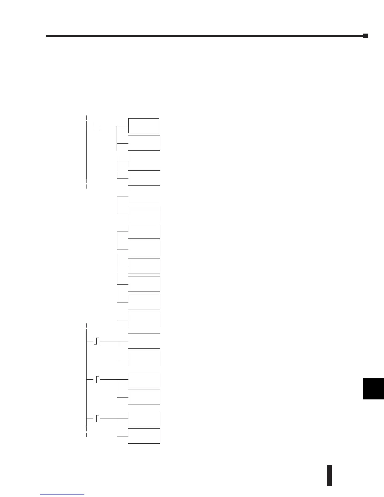
LD
K
Rung 1, ModuleConfiguration:
Input: binarydataformat, 1channel.
Output:binary dataformat, 1channel.
Modulelocation: loc al base,slot 3.
Input data 1stmemory location: V2000.
Output data1st memory location: V2020.
Inputresolution: 16 bit channel1.
Input/Output range: 0--10V in, 0--10V out.
InputTrack and Hold: resetchannel1.
8181
OUT
V7663
LDA
O2000
OUT
V7673
LDA
O2020
OUT
V7703
LD
K2
OUT
V36403
LD
K3
OUT
V36423
LD
K2
C1
OUT
V36423
LD
K3
OUT
V36423
C3
C5
LD
K1
OUT
V36423
C1 loadsvalue of 2(binary 10) into theTrack and Hold Selection
register. This sets input channel1forTrack andHoldMaximum
Value. As the analog valuevaries, only ameasured value higherthan
thepreviously stored valuewillbewrittentoV2000.
C3 loadsavalue of 3(binary 11)intothe Trackand Hold Selection
register. This sets inputchannel1forTrack and Hold ResetValue.
Real-- time measur ed values will be writtentoV2000 until another
Track and Hold Selectionismade.
C5 loadsvalue of 1(binary 01)intothe Track and Hold Selection
register. This sets inputchannel1forTrack and Hold MinimumValue.
As the analog value varies,onlyameasured valuelower than the
previously stored stored will be writtentoV2000.
LD
K101
OUT
V36413
 Loading...

