DL205 Analog Manual, 7th Edition Rev. D
5-11
Chapter 5: F2-08AD-2, 8-Ch. Analog Voltage Input
1
2
3
4
5
6
7
8
9
10
11
12
13
14
A
B
C
D
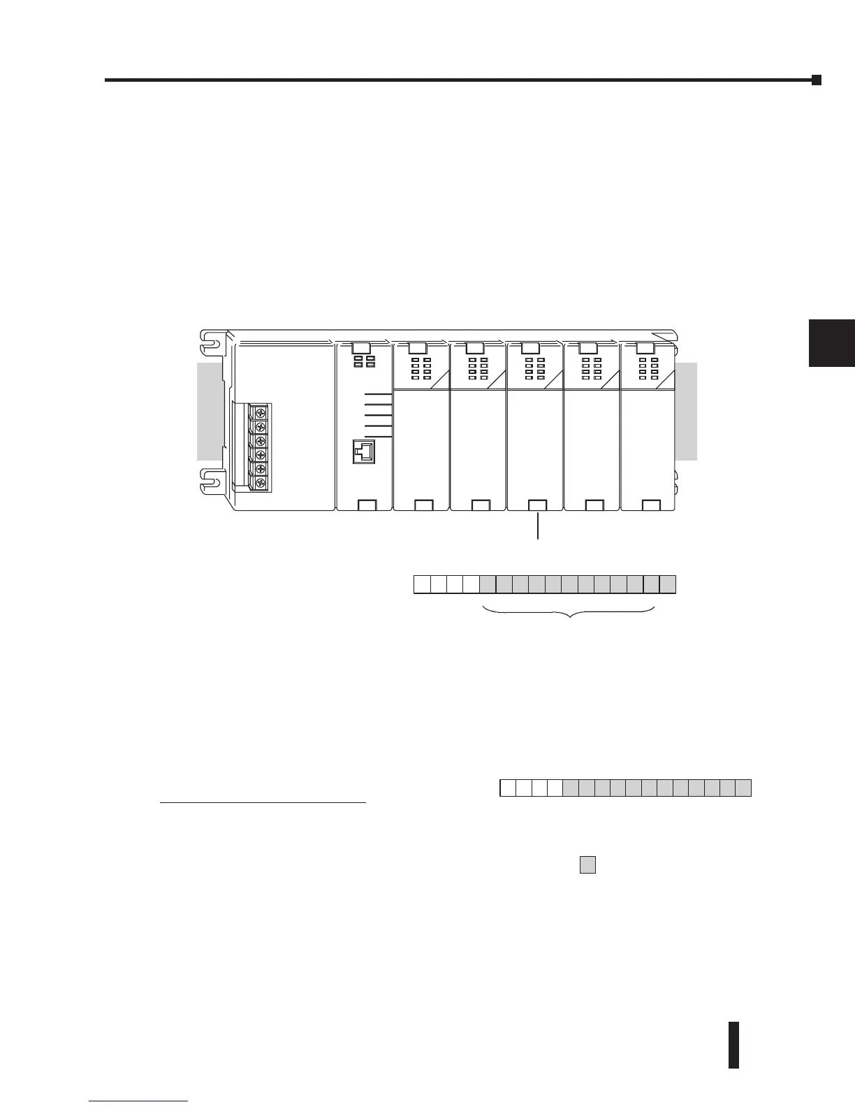
Understanding the Input Assignments
It was mentioned earlier in this chapter that the F2-08AD-2 module appears as a 16-point
discrete input module to the CPU. These points can be used to obtain:
• an indication of which channel is active
• the digital representation of the analog signal
• module diagnostic information
Since all input points are automatically mapped into V-memory, it is very easy to determine the
location of the data word that will be assigned to the module.
Within these word locations, the individual bits represent specific information about the analog
signal.
Analog Data Bits
The first twelve bits represent the analog
data in binary format.
Bit Value Bit Value
0 1 6 64
1 2 7 128
2 4 8 256
3 8 9 512
4 16 10 1024
5 32 11 2048
1
2
3
4
5
6
7
8
9
10
11
12
13
14
A
b
C
D
1
5
V40401
BSLBSM
01
4
1
3
1
2
1
1
1
0
987654321
= databits
X
3
 Loading...

