DL205 Analog Manual, 7th Edition Rev. D
7-10
Chapter 7: F2-04THM, 4-Channel Thermocouple Input
1
2
3
4
5
6
7
8
9
10
11
12
13
14
15
B
C
D
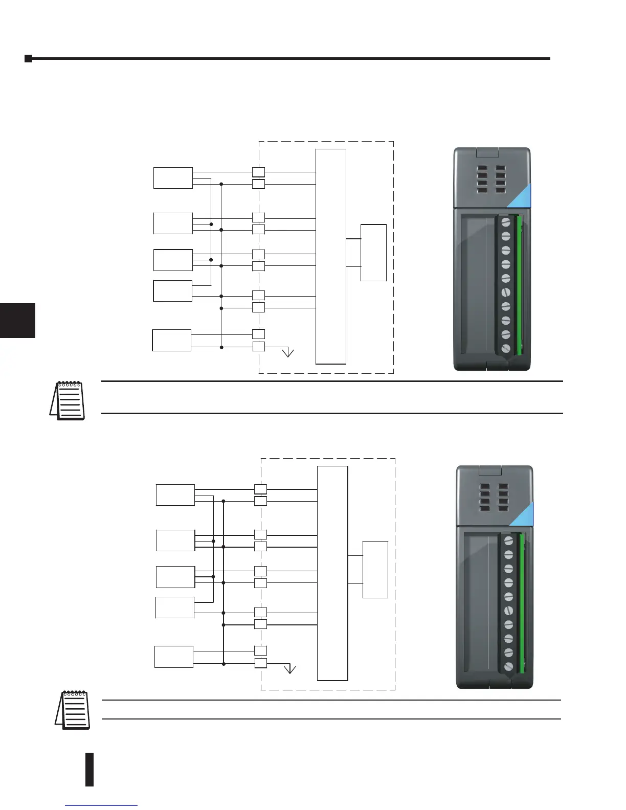
Wiring Diagrams
Use the following diagrams to connect the field wiring.
1
2
3
4
5
6
7
8
9
10
11
12
13
14
15
b
C
D
Voltage
Transmitter
Analog Mux
ADC
Voltage
Transmitter
Voltage
Transmitter
0V
Transmitter
Supply
+
--
24
VDC
+24VDC
Module Supply
CH1+
CH2+
CH3+
CH4+
CH1
CH2
CH3
CH4
0V
Analog Mux
ADC
0V
+
--
+24VDC
CH1+
CH2+
CH3+
CH4+
CH1
CH2
CH3
CH4
0V
Voltage
Transmitter
Voltage
Transmitter
Voltage
Transmitter
Transmitter
Supply
24
VDC
Module Supply
Thermocouple Input Wiring Diagram
CH1 +
CH1
CH2 +
CH2
CH3 +
CH3
CH4 +
CH4
+24V
0v
IN
F2-04THM
TEMP
VOLT
THERMOCOUPLE mV
0-5, -5-+5VDC
18-26.4VDC, 60mA
Voltage Input Wiring Diagram
CH1 +
CH1
CH2 +
CH2
CH3 +
CH3
CH4 +
CH4
+24V
0v
IN
F2-04THM
TEMP
VOLT
THERMOCOUPLE mV
0-5, -5-+5VDC
18-26.4VDC, 60mA
NOTE: Terminate shields at the respective signal source. Also, connect unused channels to a common terminal (0V,
CH4+, CH4).
NOTE: Connect unused channels to a common terminal (0V, CH4+, CH4).
 Loading...

