DL205 Analog Manual, 7th Edition Rev. D
3-22
Chapter 3: F2-04AD-2 , F2-04AD-2L, 4-Channel Analog Voltage Input
1
2
3
4
5
6
7
8
9
10
11
12
13
14
A
B
C
D
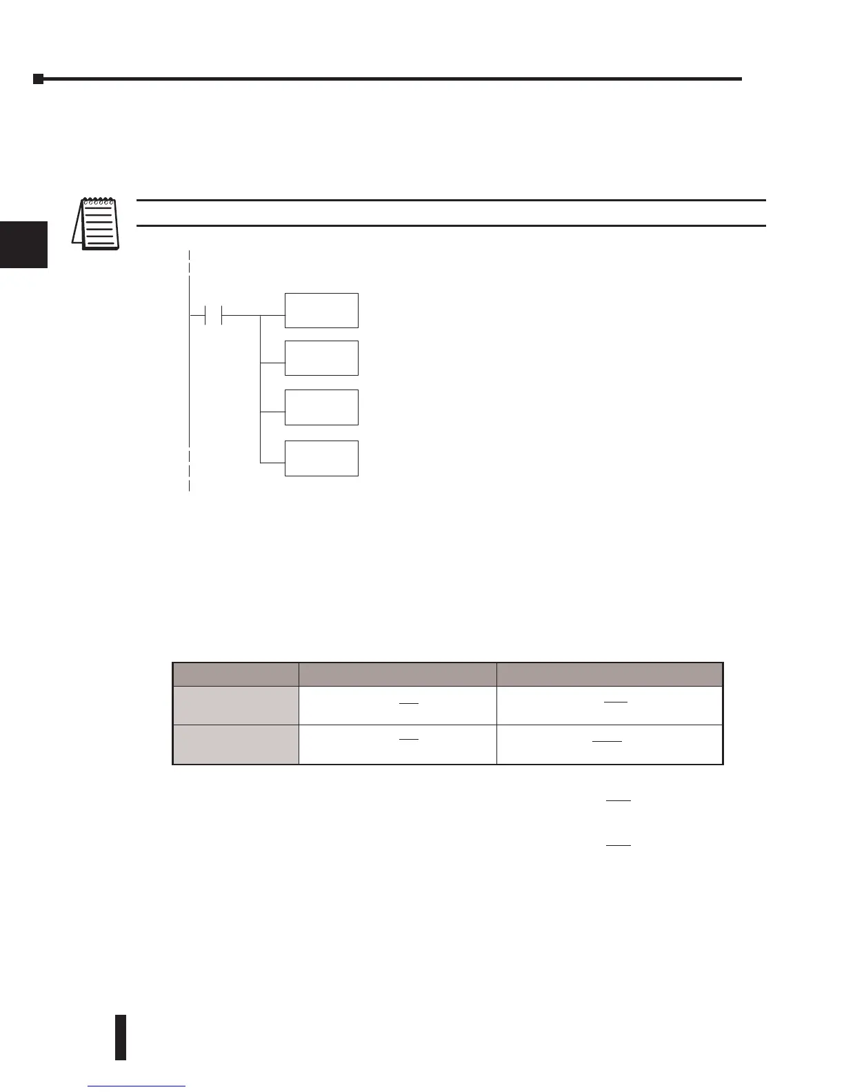
The Conversion Program
The following example shows how to write the program to perform the engineering unit
conversion from input data formats 0–4095. This example assumes the raw input data read at
V2000 is in BCD format.
NOTE: This example uses SP1, which is always on, but any permissive contact such as, X, C, etc., can be used.
Analog and Digital Value Conversions
Sometimes it is useful to be able to quickly convert between the signal levels and the digital
values. This is especially helpful during machine startup or troubleshooting. Remember, that
this module does not operate like other versions of analog input modules. The bipolar ranges
use 0–4095 for both positive and negative voltages. The sign bit allows this, which actually
provides better resolution than those modules that do not offer a sign bit. The following table
provides formulas to make this conversion easier.
As an example, if the range being used is -10V – +10V
and the measured signal is 6V, use the formula to the
right to determine the digital value that is stored in the
V-memory location that contains the data.
1
2
3
4
5
6
7
8
9
10
11
12
13
14
A
b
C
D
LD
V2000
SP1
MUL
K1000
DIV
K4095
When SP1 is on, load channel1datatothe accumulator.
Multiply theaccumulator by 1000(to startthe conversion).
Divide theaccumulator by 4095.
OUT
V2010
Storethe result in V2010.
Range If the digital value is known If the analog signal level is known.
0 – 5V
-5V – +5V
A =
5D
4095
D =
4095
(A)
5
0 – 10V
-10V – +10V
A =
5D
4095
D = 4095
ABS(A)
10
D =
4095
(A)
10
D =
4095
(6V)
10
D = (409.5) (6)
D = 2457
 Loading...

