DL205 Analog Manual, 7th Edition Rev. D
14-19
Chapter 14: F2-4AD2DA 4-Ch. In / 2-Ch. Out Analog Combination
1
2
3
4
5
6
7
8
9
10
11
12
13
14
A
B
C
D
Single Input Channel Selected (Multiplexing)
Since it isn’t necessary to determine which channel is selected, the single channel example
shown below can be implemented in the user program.
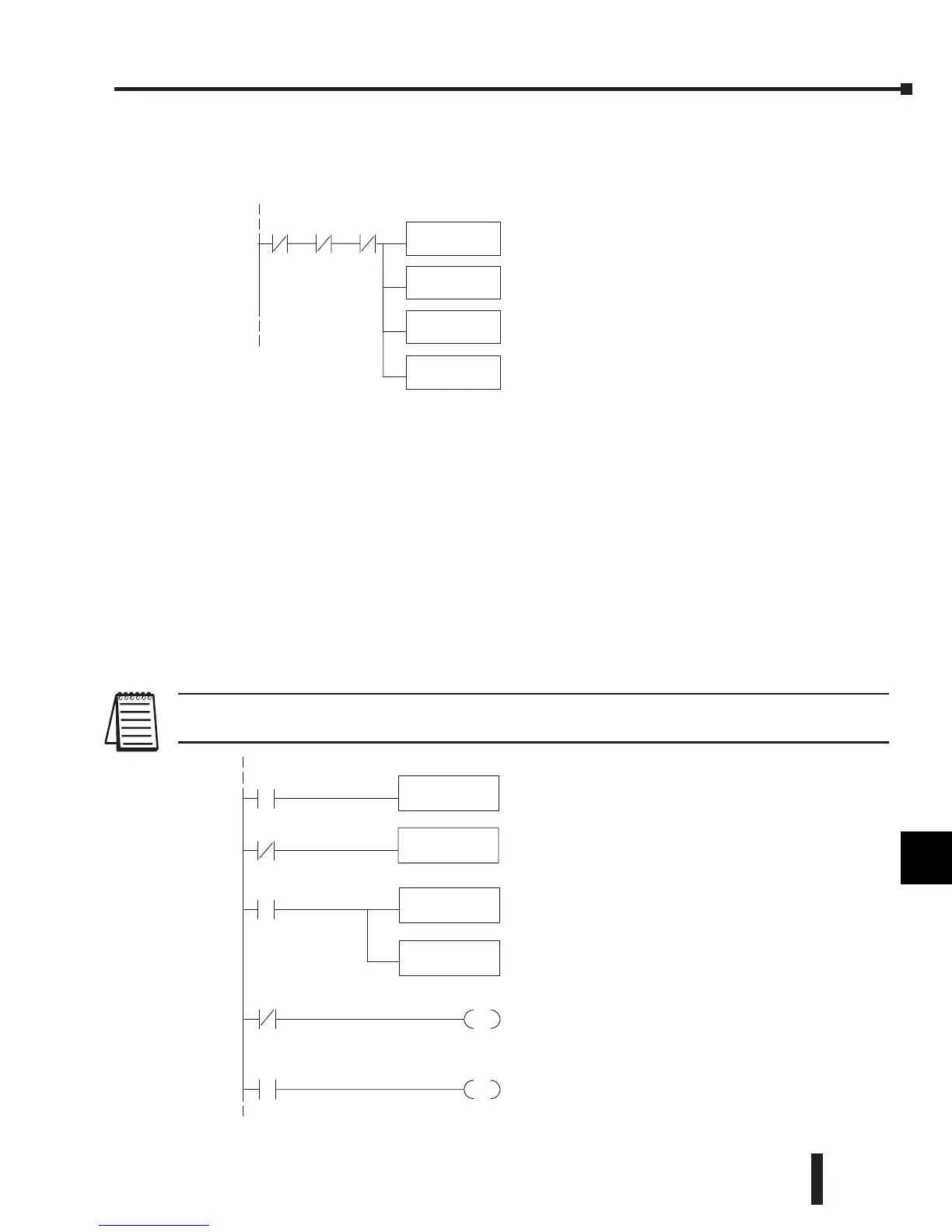
Write Output Values (Multiplexing)
Since all channels are multiplexed into a single data word, the control program can be setup
to determine which channel to write the data to. Since the module appears as Y output points
to the CPU, it is simple to use the channel selection outputs to determine which channel to
update.
Note, this example is for a module installed in slot 3, as shown in the previous examples. The
addresses used would be different if the module was used in a different slot. These rungs can
be placed anywhere in the program or if stage programming is being used, place them in a
stage that is always active.
This example is a two-channel multiplexer that updates each channel on alternate scans. Relay
SP7 is a special relay that is On for one scan, then Off for one scan. This multiplexing example
can be used with all of the DL205 CPUs.
NOTE: Binary data must be sent to the output module. If the data is already in binary format, do not use the BIN instruction
shown in this example.
1
2
3
4
5
6
7
8
9
10
11
12
13
14
A
b
C
D
It is usually easier to performmath operations in
BCD. Youcan leave out this instruction if your
application does not requireit.
This instructionmasks thechannelidentification
bits.Without this,the values used will not be
correct so do notforget to include it.
Loadsthe complete datawordintothe accumulator.
TheV-memorylocation depends on the I/O
configuration. SeeAppendix Afor thememorymap.
SP7
SP1
Send data to V-memory assigned to themodule.
BIN
Convertthe data to binary(youmustomitthisstepif
youhaveconvertedthe data elsew here).
SP1 is always on.
OUT
V40501
LD
V2000
SP7
LD
V2001
Loadsthe datafor channel 2 intothe accumulator.
TheOUT instruction sends the datatothe module.Our
examplestartswithV40501,but theactualvalue
dependsonthe location of themoduleinyour
application.
SP7
OUT
Y34
SP7
Select thechannelto update.
Selects channel1for update when Y34isOFF
(Y35--ON deselects channel 2).Note, Y34and Y35are
used due to thepreviousexamples. If themodule was
installedinadifferent I/Oarrangement, theaddresses
would be different.
Selects channel2for update when Y35isOFF
(Y34--ON deselects channel 1).Note, Y34and Y35are
used due to thepreviousexamples. If themodule was
installedinadifferent I/Oarrangement, addresses
 Loading...

