DL205 Analog Manual, 7th Edition Rev. D
6-16
Chapter 6: F2-04RTD 4-Channel RTD Input
1
2
3
4
5
6
7
8
9
10
11
12
13
14
A
B
C
D
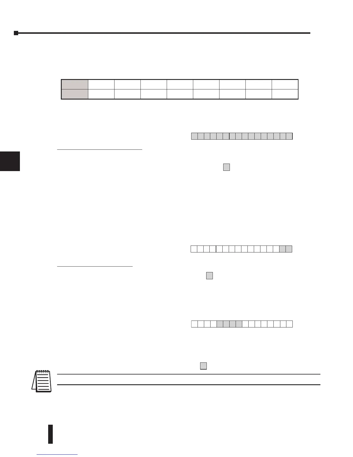
When a DL230 CPU is used, the input points must start on a V-memory boundary. To use
the V-memory references required for a DL230 CPU, refer to the table below. The first input
address assigned to a module must be one of the X inputs shown. The table also shows the
V-memory addresses that correspond to these X inputs.
Analog Data Bits
The first 16 bits represent the analog
data in binary format.
Bit Value Bit Value
0 1 8 256
1 2 9 512
2 4 10 1024
3 8 11 2048
4 16 12 4096
5 32 13 8192
6 64 14 16384
7 128 15 32768
Active Channel Bits
The active channel bits represent the
multiplexed channel selections in binary
format.
Bit 1 Bit 0 Channel
0 0 1
0 1 2
1 0 3
1 1 4
Broken Transmitter Bits
(Multiplexing Ladder Methods)
The broken transmitter bits are on when
the corresponding RTD is open.
NOTE: The broken transmitter bits only function using the Multiplexing method.
1
2
3
4
5
6
7
8
9
10
11
12
13
14
A
b
C
D
X
X0 X20 X40 X60 X100 X120 X140 X160
V
V40400 V40401 V40402 V40403 V40404 V40405 V40406 V40407
 Loading...

