DL205 Analog Manual, 7th Edition Rev. D
15-24
Chapter 15: F2-8AD4DA-1, 8-Ch. In / 4-Ch. Out Analog Current Combination
1
2
3
4
5
6
7
8
9
10
11
12
13
14
15
B
C
D
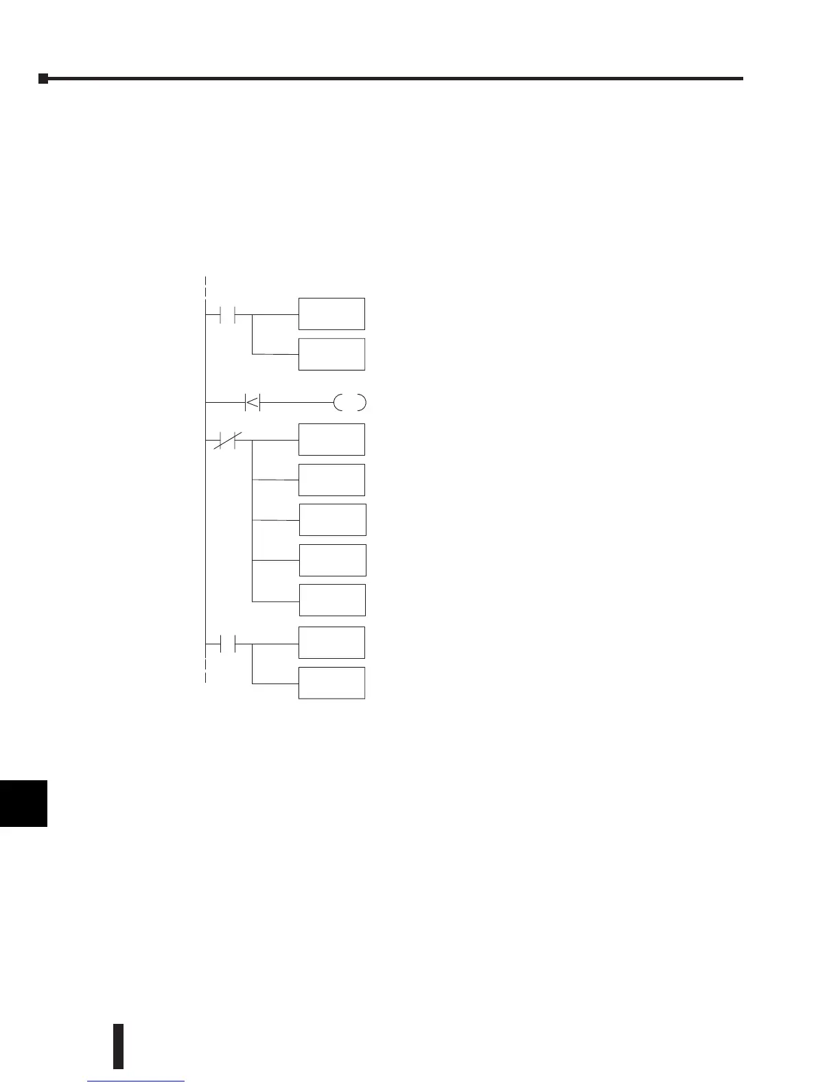
Input Engineering Unit Conversion Example 3:
Data format = BCD,
Channel 1 data memory location = V2000,
Channel 1 resolution = 12 bits,
Channel 1 engineering units = 0.0–140.0 PSI,
Channel 1 input device = 4–20 mA transmitter.
1
2
3
4
5
6
7
8
9
10
11
12
13
14
15
b
C
D
SUB
V2030
MUL
K1400
Subtract 819;
12 bitdigital valuefor 4mAoffset.
(Thisrung not used if inputtransmitter is 0--20 mA.)
Multiply by 1400;
EU range X10for implieddecimal.
DIV
K3276
Divide by 3276;
12 bit digitalrange for4-- 20 mA.
(For 0--20 mA xmitter: use 4095.)
OUT
V2100
StoreinputEUvalue in V2100.
LD
V2000
C0
Loadinput channel1digitalvalue intoaccumulator.
(Ifinput notlessthan4mA.)
OUT
C0
V2000
K819
C0 is on when analog input is less than 4mA;
819=4mA@12 bits.
(This rung notusedif inputtransmitter is 0--20 mA.)
OUT
V2030
Storeinput offset value in V2030.
LD
K819
SP0
Loadconstant 819 into accumulator;
12 bit digitalvalue for4mA offset.
OUT
V2100
Storevalue of 0inV2100
(Thisrung not used if inputtransmitter is 0--20 mA.)
LD
K0
Load valueof0into accumulator.
(Ifinput less than 4mA.)
(This rung notusedif inputtransmitteris0-- 20 mA.)
C0
 Loading...

